

Many of us who have worked with Analog circuits would have often come across the terms voltage source and current source in a circuit design. While anything that provides a constant voltage like a simple 5V USB output or a 12V adapter can be considered as a voltage source, the term current source always seems to remain a mystery. And many circuits, especially the one involving Op-Amp or switching circuits would require you to use a constant current source to make the design work. So what is meant by current source? How will it work and why is it needed?
In this tutorial we will find answers to these questions and we will also build and test a simple Constant current source circuit using transistor. The circuit used in this tutorial will be able to able to deliver a constant current of 100mA to your load but you can modify it using a potentiometer as per your design requirements. Interesting right! So let’s get started.
What is Constant Current (CC) Source?
Normally when a power supply unit drives a load there can be two possible modes of operation, one is by Constant Voltage (CV) mode of operation, and the other by Constant Current (CC) mode operation.
In CV mode, the power supply makes the output voltage constant and changes the output current as required by the load resistance. The best example will be your 5V USB port, where the output voltage is fixed at 5V but based on the load the current will vary. If you connect a small led it will draw less current and if you connect a bigger one it will draw more current but the voltage across the LED will always be 5V.
In CC mode, an ideal current source power supply makes the output current constant and varies the output voltage as required by the load resistance. An example for this will be 12V battery charger in CC mode where charging current will be fixed by voltage will be varied. In case where your battery is 10.5V if you connect it to a 1A 12V battery charger, your output current from charger will always be 1A but the output voltage will be varied to maintain this 1A charging current. So this is where Constant current circuits are required, other example can be constant current LED driver circuit where current though an LED has to be constant.
Simple 100mA Constant Current Source using Transistor
In this project, we will build a simple transistor constant current source generator using only 4 components. It is a very inexpensive circuit that can provide 100mA constant current source using a 5V power supply. It will also have a potentiometer to control the current output from 1 to 100mA range. It will provide a steady current even if there are changes in load resistance. This will be helpful to use when a circuit needs steady current supply without fluctuations. Previously we have also built other type of current source circuit called the Howland Current Pump Circuit, and the Current Mirror circuit you can also take a look at them if interested. Now, lets look at the materials required for this project.
Materials Required:
- TL431
- BC547
- 2k resistor 1%
- 10k variable resistor
- 22R 1% resistor
- A 5V DC adapter or PSU unit.
- Different kind of load resistance as per required.
- A breadboard and hook up wires
- Multimeter for testing.
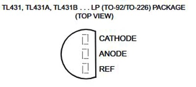
As stated in the above BOM, the circuit consists of only two active components, TL431 and BC547. TL431 is a shunt regulator that uses a 2.5V voltage reference. It supports 1-100mA of cathode current for shunt related operations. The package of this component is the same as the generic through-hole transistor. Other components are passive components. Resistors need to be in 1% tolerance for the accurate output.
Constant Current Source Circuit Diagram:
The circuit diagram for constant current source using transistor project is shown below.

The above circuit is entirely connected in a 5V lin. The output load needs to be connected between the Output and the GND connection. In the above schematic, BC547 is working as a pass transistor, more on that will be discussed in the working section.
Important calculations for constant current circuit
The output current of the above circuit is dependent on the below formula – which can be used to calculate the output current of the constant current source circuit.
Iout = Vref/R4 + IKA
For this circuit,
Iout = 100 mA (.100A)
Vref = 2.5V
IKA = 1mA (.001A) [Note: minimum bias current]
So,
Iout = Vref/R4 + IKA
.100 = 2.5/R4 + .001
.100 - .001 = 2.5/R4
R4 = 2.5/.099
R4 = 25 ohms (Approx)
Available lowest closer value of the R4 is 22 Ohms. Now, the variable resistor or the potentiometer value can be found using the same formula. In previous, the maximum available current 100mA was achieved by 22 Ohms resistor. This time the potentiometer will reduce the current output to the lowest level.
Since the minimum cathode current is required for the TL431 is 1mA, it is good to assume the lowest current will be 2mA. Therefore, by using the same formula,
Iout = Vref/VR1 + IKA
.002 = 2.5/VR1 + .001
.002 - .001 = 2.5/VR1
.001 = 2.5/VR1
VR1 = 2.5K
Thus, available lowest closer value 2.2k potentiometer can be used for the current control. The last calculation is to calculate the bias resistor R1 value using the below formulae.
R1 = Vin/(Iout/hFE + IKA)
For this circuit,
Iout = 100mA (.100A)
Vin = 5V
hFE = 100(Maximum)
IKA = 1mA (.001A) [Note: minimum bias current]
R1 = Vin/(Iout/hFE + IKA)
R1 = 5/(.100/100 + .001)
R1 = 2.5 k ohms
Thus, the available lowest closer value R1 can be 2.2k.

Constant Current Circuit Working:
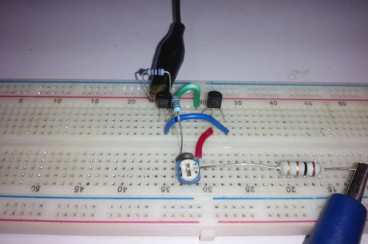
The transistor BC547 is acting as a pass transistor that is controlled by the bias resistor R1 and the shunt regulator TL431. The transistor base is actually connected across a current divider. This current divider circuit is made using the bias resistor and the shunt regulator. TL431 regulates the constant current by sensing the reference voltage and controlling the pass transistor BC547. The circuit is constructed on a breadboard as shown below.
Testing the Constant Current Source Circuit
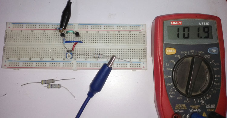
Once the board is ready I powered up my circuit using 5V DC supply and started testing it. I used different loads (different values of resistor) on the output side and made sure the current always remained constant. I used my multimeter to measure the output current of my circuit and it was always around 100mA as shown in the picture below
The complete testing video can be found at the bottom of this page. If you have any questions leave them in the comment section below or use the forums for other technical quires.
Application of Constant Current Source Circuits
In the LED lighting system, constant current source is required for LED driving-related operations. As well as in portable devices, battery charging circuits use constant current sources. A small list of applications where constant current source is used is listed below
- Amplifier system.
- Solar systems
- Electromagnets
- Motor system for steady speed.
- Hall Effect sensors.
- Regulator circuits to bias zener diodes.

This circuit is an absolute disaster. The first thing you will do is blow up the 2k2 pot.