
A Secure Digital (SD) card is used to store information in many electronic devices, especially smartphone and digital cameras. But did you know that you can read and write information on an SD card with the help of a simple 8-bit microcontroller? You heard that right, it's possible to do so, this opens up a bag full of opportunities in embedded systems and design. Since the price of an SD card is far better than any other storage option, it can be used to store and log data for days. this makes the logging capabilities much simpler. This is one example, you can do a lot more with an SD card.
In one of our previous articles, we have shown an Arduino Based Data Logger, which we used to store temperature and humidity data. But doing this with a PIC microcontroller is much more difficult than doing it with an Arduino. So, in this article, we are going to show you how you can simply interface an SD card module with PIC microcontroller and store data inside it. We have also built many other projects with PIC Microcontroller like:
- Robotic Arm Control using PIC
- IoT Based Web Controlled Home Automation
- PIC Microcontroller Based Heart Beat Monitor
You can check those out if you are interested in learning more about PIC.
Understanding Different Types of SD Card?
Secure Digital cards or SD cards is a non-volatile memory card format developed by the SD Associations (SDA) for use in portable devices. Secure Digital card can be subdivided into four categories, a list of which is shown below.
SDSC (Secure Digital Standard Capacity):
The most basic and common card you can find in the market is the SDSC card. It stands for Secure Digital Standard Capacity; this type of card has a maximum capacity of 2GB and it uses FAT16 Filesystem. Other than that, this type of card has a maximum transfer capacity of 12.5MB/s.
SDHC (Secure Digital High-Capacity):
Next, on the list is another most common card known as the SDHC or Secure Digital High-Capacity card. This card has a maximum capacity of 32GB and supports an upgraded FAT32 Filesystem. In a general scenario, this card is supported by a bus speed of 12.5MB/s to 25MB/s, but it supports up to 3938MB/s depending on Bus interfaces (UHS-I, UHS-II, UHS-III, SD-Express).
SDXC (Secure Digital eXtended-Capacity):
Next, we have our SDXC card or Secure Digital eXtended-Capacity, this card comes with a max capacity of 2TB and it can support both FAT32 and exFAT Filesystem. The default bus speed of this card is 12.5MB/s to 25MB/s but it supports up to 3938MB/s depend on Bus interfaces (UHS-I, UHS-II, UHS-III, SD-Express)
SDUC (Secure Digital Ultra-Capacity):
Next, on the line, we have our most recently upgraded card or the SDUC card, which stands for Secure Digital Ultra-Capacity. This card has a maximum capacity of 128TB and it can only support the exFAT Filesystem. It also has a default bus speed of 12.5MB/s to 25MB/s but depending upon the bus type, it can supports up to 3938MB/s (UHS-I, UHS-II, UHS-III, SD-Express).
SDIO (Secure Digital Input Output):
SDIO is a type of Secure Digital card interface. It can be used as an interface for input or output devices as per capacity and Bus speed.
SD cards are also classified by their “Writing Speed” and “Physical Size”
1. Classified by “Writing Speed”
- Speed Class
- The graphical symbol for the speed class has a number encircled with 'C' (C2, C4, C6, & C10). Like this

- Writing Speed 2MB/s to 10MB/s and Number Encircled denote the speed.
- The graphical symbol for the speed class has a number encircled with 'C' (C2, C4, C6, & C10). Like this
- UHS Speed Class
- The graphical symbol for the speed class has a number inside in the ‘U’ (U1 & U3). Like this

- Writing Speed 10MB/s & 30MB/s and Number denote the speed multiply with 10.
- The graphical symbol for the speed class has a number inside in the ‘U’ (U1 & U3). Like this
- Video Speed Class
- The graphical symbol for the speed class has a number beside the ‘V’ (V6, V10, V30, V60 & V90. Like this

- Writing Speed 6MB/s to 90MB/s and Number denote the speed.
- The graphical symbol for the speed class has a number beside the ‘V’ (V6, V10, V30, V60 & V90. Like this
- Application Performance Class
- The graphical symbol for the speed class has a number beside the ‘A’ (A1 and A2). Like this

- Writing Speed 10MB/s.
- The graphical symbol for the speed class has a number beside the ‘A’ (A1 and A2). Like this
2. Classified by “Physical Size”
- Standard (32 mm × 24 mm × 2.1 mm)
- miniSD (21.5 mm × 20 mm × 1.4 mm)
- microSD (15 mm × 11 mm × 1 mm)
Understanding the Function of Different Pins of an SD Card
In general, the SD card has nine pins, but only seven of these pins are used to communicate with an SD card in SPI mode. The image of the SD card MicroSD card and the SD card module is shown below.
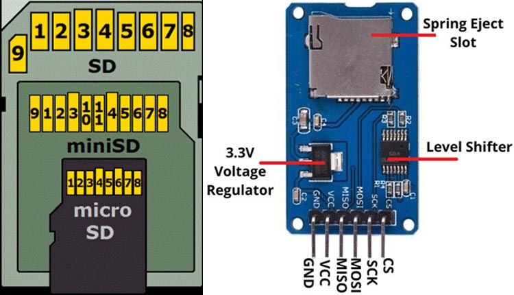
A standard SD card can be operated in 3 modes:
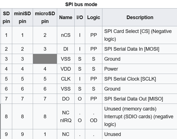
1. SPI Mode Pin Configuration
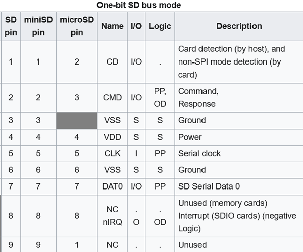
2. One-bit SD mode Pin Configuration
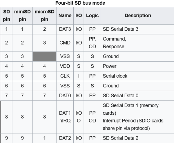
3. Four-bit SD Mode Pin Configuration
In this project, we are going to communicate with the SD card through SPI. The operation frequency is in between 100kHz to 400kHz.
Components Required to Communicate SD Card with PIC Microcontroller
The component required to build this project is very generic and most of these can be found in your local hobby store. A list of required components is given below.
- PIC Microcontroller (PIC18F46K22)
- SD card module (with 3.3 voltage regulator and logic level shifter)
- Resistors (3x3.3K and 3x2.2k) for voltage Step Down (if use SD card directly)
- 20MHz crystal oscillator
- 33pf Capacitor - 2Nos
- 4.7k, 100E Resistor
- PicKit3
- Led any color
- Push Button
- Bread Board
- Jumper wires
- 12V adapter to Power up the PIC and SD card module
Schematic used to Connect the SD with PIC Microcontroller
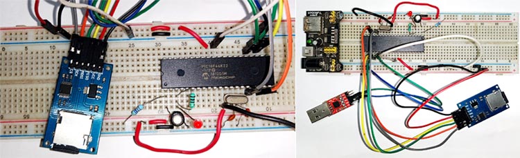
A circuit diagram for PIC Microcontroller Based Data Logger is given below.

We are using PIC18F46K22 as the brain to communicate with the SD card module. We already know that the operating voltage of a PIC microcontroller is 5V, which is not suitable for the SD card. Because the SD card operates in the 3.3v voltage range, for that reason we have used some potential divider to lower the SD card input voltage.
We use 2.2k and 3.3k resistors to create the potential divider circuit.
SD Card input voltage = 5v x (3.3k/ (2.2k+3.3k)) = 3v
Program to Establish Communication Between SD Card and PIC Microcontroller
In this project, we use Chan’s FatFs Generic FAT File System Module library for reading and writing the data onto the SD card and use the Microchip Code Configurator(MCC) to configure the program for (PIC18F46K22). The complete program can be found at the bottom of this page.
Those libraries mentioned above are included at the beginning of the code.
#include "mcc_generated_files/mcc.h"
#include "ff.h"
Next, define 2 variable fatFs and file is used to access the area of the SD card.
FATFS fatFs;  /* FatFs work area needed for each volume */
FIL file;    /* File object needed for each open file */
Next, we define a call back function to blink an LED, we do this with the help of Timer0. We calculate it so that the LED will blink once every 1sec.
void blink_led(){
            IO_RA1_Toggle();
}
In the main() loop, we call the SYSTEM_Initialize() function to initialize the system peripheral like (INTERRUPT, Pin, Timer0, Uart, SPI1). And enable the Global and Peripheral Interrupt.
void main(void)
{
            UINT bw;
            // Initialize the device
            SYSTEM_Initialize();
            // If using interrupts in PIC18 High/Low Priority Mode you need to enable the Global High and Low Interrupts
            // If using interrupts in PIC Mid-Range Compatibility Mode you need to enable the Global and Peripheral Interrupts
            // Use the following macros to:
            // Enable the Global Interrupts
            INTERRUPT_GlobalInterruptEnable();
            // Disable the Global Interrupts
            //INTERRUPT_GlobalInterruptDisable();
            // Enable the Peripheral Interrupts
            INTERRUPT_PeripheralInterruptEnable();
            // Disable the Peripheral Interrupts
            //INTERRUPT_PeripheralInterruptDisable();
After the system initialization, we call the TMR0_SetInterruptHandler() function, to set up the callback function and then we start the Timer0.
TMR0_SetInterruptHandler(blink_led);
TMR0_StartTimer();
After all initialization, now we start the main process with the SD card. At first, we need to mount the SD card by calling the function f_mount() and store the return value into the variable called the FRESULT. By checking that stat variable, we can proceed further. So, if the stat result is FR_OK, then it means that the SD card successfully mounted otherwise it failed. So, after the SD card is successfully mounted, we now call f_open() to create a file with the name “test.txt” and then use the f_lseek() function to point the cursor at the end of the file. Now, we can call the f_write() function to write the data into that file and at the end, we call the f_close() to close the opening file in the SD card. This is how we can write inside the text file we have created earlier.
printf("\r\n============= Start Interfacing with SD Card =============\r\n");
            FRESULT stat = f_mount(&fatFs, "", 1);
            if (stat == FR_OK) {    /* Mount SD */
            printf("SD Card Mount Successful\r\n");
            SD_LED_SetHigh();
             if (f_open(&file, "Sd_test.txt", FA_OPEN_ALWAYS | FA_READ | FA_WRITE) == FR_OK) {    /* Open or create a file */
            printf("Create a file successful\r\n");
                         if ((file.fsize != 0) && (f_lseek(&file, file.fsize) != FR_OK)) goto endSD;    /* Jump to the end of the file */
                         f_write(&file, "Hello Guys!\r\n", 13, &bw);
            f_write(&file, "This is text message written to SD card. For more information, please visit www.circuitdigest.com\r\n", 99, &bw);
                         endSD: f_close(&file);                                                                                    /* Close the file */
            SD_LED_SetLow();
             }else{
            printf("Create a file unsuccessful\r\n");
            SD_LED_SetLow();
            }
    }else{
            printf("SD Card Mount UnSuccessful\r\n ------ FRESULT %d ------\r\n");
            }
            printf("\r\n============= Finish Interfacing with SD Card ============= \r\n\r\n\r\n\r\n");
This is how we can interface the SD card with the PIC microcontroller to store data into the SD card.

Testing and Debugging the Communication Process
Once the circuit and code were complete, we tested the circuit with the help of the debug log that we have put in our code. As you can see, we have used a USB to UART converter to log debug data in our serial monitor window for that we have used PuTTY.
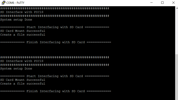
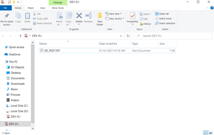
Once we see 'Create a file successful' message, we then take out the SD card from the SD card module and directly put it into our PC to verify if the file was created or not, and sure enough, the file was created successfully.
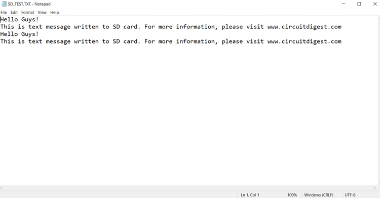
We opened the file and checked if the message we put in was there or not. It was there and this proved that our code was working correctly.
I hope you liked the article and learned something new, if you have any questions regarding the article do comment below, or you can use our forum to get a speedy response.
Complete Project Code
#include "mcc_generated_files/mcc.h"
#include "ff.h"
FATFS fatFs; /* FatFs work area needed for each volume */
FIL file; /* File object needed for each open file */
void blink_led(){
    IO_RA1_Toggle();
}
/*
                         Main application
 */
void main(void)
{
    UINT bw;
    // Initialize the device
    SYSTEM_Initialize();
    // If using interrupts in PIC18 High/Low Priority Mode you need to enable the Global High and Low Interrupts
    // If using interrupts in PIC Mid-Range Compatibility Mode you need to enable the Global and Peripheral Interrupts
    // Use the following macros to:
    // Enable the Global Interrupts
    INTERRUPT_GlobalInterruptEnable();
    // Disable the Global Interrupts
    //INTERRUPT_GlobalInterruptDisable();
    // Enable the Peripheral Interrupts
    INTERRUPT_PeripheralInterruptEnable();
    // Disable the Peripheral Interrupts
    //INTERRUPT_PeripheralInterruptDisable();
    TMR0_SetInterruptHandler(blink_led);
    TMR0_StartTimer();
    SD_LED_SetLow();
    printf("##########################################################\r\n");
    printf("SD Interface with PIC18\r\n");
    printf("##########################################################\r\n");
    printf("System setup Done\r\n");
    printf("\r\n============= Start Interfacing with SD Card =============\r\n");
    FRESULT stat = f_mount(&fatFs, "", 1);
    if (stat == FR_OK) { /* Mount SD */
        printf("SD Card Mount Successful\r\n");
        SD_LED_SetHigh();
if (f_open(&file, "Sd_test.txt", FA_OPEN_ALWAYS | FA_READ | FA_WRITE) == FR_OK) { /* Open or create a file */
            printf("Create a file successful\r\n");
if ((file.fsize != 0) && (f_lseek(&file, file.fsize) != FR_OK)) goto endSD; /* Jump to the end of the file */
f_write(&file, "Hello Guys!\r\n", 13, &bw);
            f_write(&file, "This is text message written to SD card. For more information, please visit www.circuitdigest.com\r\n", 99, &bw);
endSD: f_close(&file); /* Close the file */
            SD_LED_SetLow();
}else{
            printf("Create a file unsuccessful\r\n");
            SD_LED_SetLow();
        }
}else{
        printf("SD Card Mount UnSuccessful\r\n ------ FRESULT %d ------\r\n");
    }
    printf("\r\n============= Finish Interfacing with SD Card ============= \r\n\r\n\r\n\r\n");
while (1) {
// Add your application code
}
}
/**
 End of File
*/
Comments
can you provide the complete…
can you provide the complete code ..?

hello can you share the project files in mplabx?
hola puedes compartir el los archivos del proyecto en mplabx?