

There are times when you need something to happen on time and that’s where timers and timer interrupts come to play. A timer is a kind of interrupt. It is like a simple clock that is used to measure and control time events providing a precise time delay. Most microcontrollers have inbuilt timers which are used not only to generate time delays but also as a counter. This characteristic of the timer is used for many applications. The timers in the microcontroller are controlled by special function registers that are assigned for timer operations.
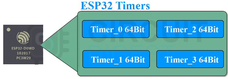
The ESP32 chip contains two hardware timer groups. Each group has two general-purpose hardware timers. They are all 64-bit generic timers based on 16-bit prescalers and 64-bit up / down counters which are capable of being auto-reloaded.
Timer Interrupts
Timer Interrupts are an effective way to ensure timed events happen to the millisecond, allowing for fine-tuned clock or PWM operations, or just supplying a reliable pulse to an LED. The timer interrupts are the software interrupts generated by the timer. Timer interrupts allow you to perform a task at very specifically timed intervals regardless of what else is going on in your code. They are similar to external interrupts, but instead of being triggered by an external event, they are triggered by a timer. Once triggered, they will interrupt the thread of execution after the current instruction completes, will call the ISR, and will return to the next instruction from where it left off when it has finished, just like hardware or external interrupt. Here is an image demonstrating the Timer concept.
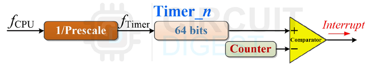
As these timers are hardware-based, all timing is related to the clock of the timer. The timer speed can be determined by the following formula-
timer speed (Hz) = Timer clock speed (Mhz) / prescaler
For example, the speed of a timer in an ESP32, which is running at a clock frequency of 80MHz, will be 80MHz or 8000000MHz for a set prescaler value of 1 and will be 1MHz or 1000000Hz for a prescaler value of 80.
The prescaler is what the above frequency is divided by to form a "tick" of the timer (increment its counter). The ISR is then configured to trigger after a specific number of ticks. The following image shows the process flow with a timer interrupt.
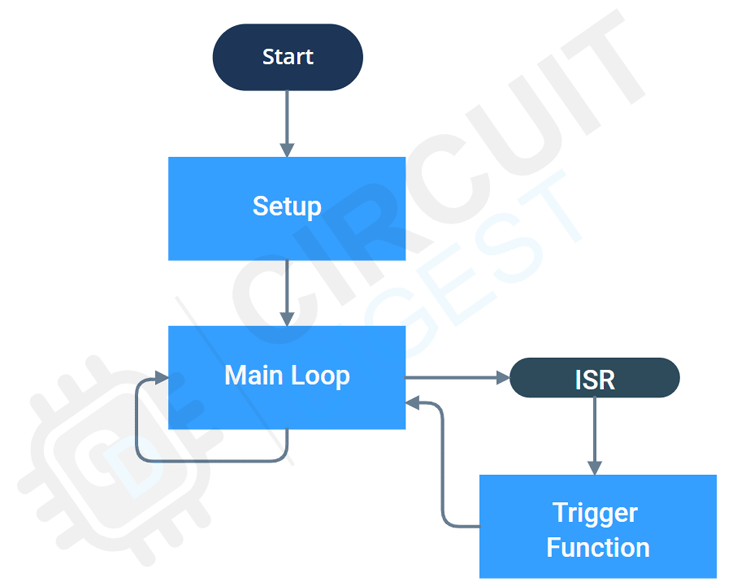
Just like a hardware interrupt the timer interrupts are also the best way to run non-blocking functions at a certain interval. For that, we will configure and attach a particular timer interrupt to a specific ISR in the setup function. The controller will execute the main loop continuously. Whenever a timer interrupt is generated, the microcontroller will pause the main loop and will proceed with the execution of the Interrupt Service Routine or ISR. Once the ISR is finished executing, the microcontroller will resume the main loop from where it was paused. This process will repeat for every Timer Interrupt.
Commonly Asked Questions about ESP32 Timer Interrupts
Q. How many Timers do ESP32 have?
The ESP32 offers four 64-bit timers.
Q. How to use Timer interrupt in ESP32?
You can attach the desired timer to an interrupt and can assign an ISR for the same
Q. How does the ESP32 timer work?
The timer uses a counter which counts at a certain speed depending upon the clock frequency and the prescaler value. This counter will reset once it reaches a set value and it will trigger an interrupt. We can change the timer intervals by changing this count value
ESP32 Timer Interrupt Example – Blinking an LED
In this example, we are going to test a LED blink program. But instead of using delay, we are going to use timer interrupt. To do that, make the connections on a breadboard as shown in the below circuit diagram.

Here is the actual circuit connected on a breadboard as per the circuit diagram.
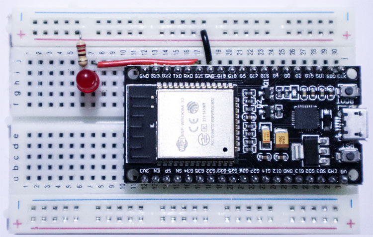
Connect the Anode of the LED to the GPIO21 and connect the cathode to GND through a 220 Ohms resistor.
ESP32 Code to Blink an LED with Timer Interrupt
Download the code attached to the bottom of this article and upload it to the ESP32. You will observe that the LED is blinking at a rate of 1Hz. Let’s discuss each part of the code.
#define LED 21
hw_timer_t *My_timer = NULL;
At the global variable area, we have defined the LED pin as GPIO21. Then we have created a pointer variable named My_timer of the type hw_timer_t in order to configure the timer.
void IRAM_ATTR onTimer(){
digitalWrite(LED, !digitalRead(LED));
}
Then we created the ISR for the timer interrupt. In the ISR we have written a function to invert the state of GPIO21. This ISR will be executed when the timer interrupt occurs.
void setup() {
pinMode(LED, OUTPUT)
My_timer = timerBegin(0, 80, true);
timerAttachInterrupt(My_timer, &onTimer, true);
timerAlarmWrite(My_timer, 1000000, true);
timerAlarmEnable(My_timer);
}
void loop() {
}
And in the Setup function, we have initialized the GPIO21 as output with the help of the pinMode macro.
My_timer = timerBegin(0, 80, true);
To initialize the timer, we are using timerbegin function with the following variables. The first one is the number of the timer we want to use (from 0 to 3, since we have 4 hardware timers), the second one is the value of the prescaler and the last one is a flag indicating if the counter should count up (true) or down (false). In this example, we are using timer 0 with the prescaler 80 and the counter to count up.
timerAttachInterrupt(My_timer, &onTimer, true);
Before enabling the timer, we need to attach it to an ISR, which will be executed when the interrupt is generated. This is done with a call to the timerAttachInterrupt function. In this example, we have attached the ISR function called onTimer to the timer interrupt.
timerAlarmWrite(My_timer, 1000000, true);
timerAlarmWrite function is used to specify the counter value in which the timer interrupt should be generated. So, for this example, we assume that we want to generate an interrupt each second, and thus we pass the value of 1000000 microseconds, which is equal to 1 second. For the third argument, we will pass the value true, so the counter will reload and thus the interrupt will be generated periodically.
timerAlarmEnable(My_timer);
At last, we are enabling the timer interrupt using the function timerAlarmEnable.
Supporting Files


Complete Project Code
#define LED 21
hw_timer_t *My_timer = NULL;
void IRAM_ATTR onTimer(){
digitalWrite(LED, !digitalRead(LED));
}
void setup() {
pinMode(LED, OUTPUT);
My_timer = timerBegin(0, 80, true);
timerAttachInterrupt(My_timer, &onTimer, true);
timerAlarmWrite(My_timer, 1000000, true);
timerAlarmEnable(My_timer); //Just Enable
}
void loop() {
}
Comments
I think the asterisk must…
I think the asterisk must not have space between it and "My_Time"
*My_Timer
Thank you, most helpful…
Thank you, most helpful.
What does the 'true' signify in 'timerAttachInterrupts'?
Should the '8000000MHz' read '8000000Hz'?
Thank you for your support…
Thank you for your support... I would like to know how many timers variables can be initialised ?

Hello, it seems that this solution does not work for me. I keep getting this error message when trying to create the pointer variable named My_timer of the type hw_timer_t in order to configure the timer.
I have copied the exact same code that is uploaded.
If anyone has had this same problem please let me know.
Thanks