
Let's say you are trying to build a remote IoT data monitoring system, the first problem you will face is how to get a proper internet connection for your device. Whether you want to get notified when someone enters your room or you want to water your plants from miles away, the internet is always a problem. In this type of situation, SIM800L GSM/GPRS Module can come in very handy. SIM800L is a very compact GSM/GPRS module that can be integrated into a lot of IoT projects due to its compact size and flexibility. This module can do anything that a normal cell phone can do like text message, make and receive phone calls and connect to the internet through GPRS and on top of that, it supports quad-band GSM/GPRS means it can work anywhere in the world.
SIM800L GSM/GPRS Module Pinout
The SIM800L GSM/GPRS module has 12 pins which are NET, VCC, RST, RXD, TXD, GND, SPK-, SPK+, MIC-, MIC+, DTR, RING.
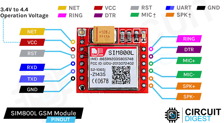
NET is a pin where you can solder the helical antenna that comes with the module.
VCC is the Power supply pin of the module and it needs to be powered anywhere from 3.4V to 4.4 volts. Connecting this module to a 5V supply will most likely destroy it and if you connect it to 3.3V it won't even run. A lithium battery or a buck converter with 2A current capacity is recommended for this module.
RST is the hard reset pin of the sim800L module. If you are having trouble communicating with this, pull the pin low for 100ms.
RXD is the RX pin for the module used in serial communication.
TXD is the TX pin for this module used in Serial communication.
GND is the Ground pin for this module; connect this pin to the Ground pin of the ESP32.
RING is the ring indicator pin of the module. This pin generally is active high. It will go low for 120ms to indicate incoming calls and can also be configured to pulse when an SMS is received.
DTR this pin can be used to put the module in sleep mode. Pulling the pin high puts the module in sleep mode and disables the serial. Pulling it low will wake the module up.
MIC+- These two pins can be used to connect an external microphone to the module.
SPK+- these two pins can be used to connect an external speaker to the module.
SIM800L GSM/GPRS Module Parts
The SIM800L module is a compact, versatile, and easy-to-use module for GSM and GPRS. The parts marking of the module is shown below.
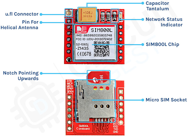
If you take a closer look at the SIM800L module there is not much on the PCB. On the front side of the PCB, we have the UFL connector and the SIM800L module itself. We also have some capacitors for decoupling and we have a 1K current limiting resistor for the LED. Finally, we have a big 100uF,16V tantalum capacitor on board. On the backside of the board we have the sim holder that is a push-to-lock type connector. This means you just need to insert a SIM card and push it for the card to work.
Overview of the SIM800L GSM/GPRS Module
At the heart of the breakout board, there is the SIM800L GSM/GPRS Module made by SimCom. As mentioned in the above pinout section, the operating voltage of this device is 3.4V to 4.4V which means you can power this module directly from a lithium polymer battery. Other than that all the usable pins are broken out to a 0.1” pin pitch that makes this module very breadboard friendly. It also has auto baud rate detection for ease of use. The module needs an external antenna to connect to the network, which is why there are two antenna options available for this board. In the package, you will get a helical antenna that you can directly solder to the NET pin of the module. But if you want to keep the antenna far away from the module board there is an option for connecting the external antenna with the onboard UFL connector. Any sim card with 2G connectivity will work with this module.
LED Status Indicator:
As we have mentioned earlier, there is an LED indicator on the top of the SIM800L module. It will blink at various rates to indicate network conditions.
Blink every one second:

If the LED on the module is blinking every second, it indicates that the module is running but it's unable to connect to the cellular network right now.
Blink every two seconds:

When the onboard LED on the monitor blinks every two seconds this means the GPRS data connection you requested is active and ready to accept requests on demand.
Blink every three seconds:

When the LED on the module is blinking every three seconds, the module is connected to a network and can send/receive voice and SMS.
Commonly Asked Questions about SIM800L GSM/GPRS Module
Q. Does SIM800L support 4G SIM?
SIM800L supports only 2G services. You can check it by inserting a 2G SIM card, I use Airtel 4G SIM and Vodafone 4G sim cards. When the sim card powers up, it tries to connect to nearest 2G carriers so it works absolutely fine with the SIM800L module.
Q. Can SIM800L connect to the internet?
SIM800L supports General Packet Radio Service (GPRS) for connecting to the internet with HTTP. The module has a built-in TCP/IP stack that can be accessed with AT commands. This can be very handy for persistent data logging on low bandwidth networks.
Q. How do I know if SIM800L is working?
SIM800L has power issues, so you need to feed the device with 1A of current for proper operations. If the power to the SIM800L is enough, the onboard LED starts blinking. If it is blinking every second, this means it is searching for a network. You will know if it's connected to the network when it blinks every three seconds. If the LED blinks very fast, this means it's connected through GPRS.
Circuit Diagram of the SIM800L GSM/GPRS Module
The circuit diagram of the SIM800L is very simple because the SIM800L IC takes care of all the complicated hardware and you only need to connect a few wires to get up and running. This schematic will be very helpful to you if you are implementing this circuit in your PCB project.

In the schematic, the sim card holder is directly connected to the SIM800L module; the power for the sim card is regulated by the SIM800 module only. And you can also see there is a big 100uF tantalum capacitor connected to the module, this is required because the module suddenly draws current spikes that sudden power requirement is fulfilled by the decoupling capacitor. Other than that, we have a tantalum capacitor and a decoupling capacitor along with the indicator LED.

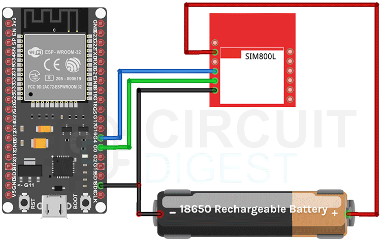
ESP32 SIM800L GSM/GPRS Module Circuit Connections
Now that we have completely understood how the SIM800 module works, we can connect all the required wires to the ESP32 Dev Board and check if the module is working properly or not. Next, we will write the code and send an SMS through the module, the connection diagram of the SIM800L module with ESP32 is shown below-
Code for Interfacing SIM800L with ESP32
The code to communicate with the SIM800L GSM/GPRS module is very simple and easy to understand. The code uses the UART2 of the ESP32 microcontroller to communicate with the SIM800 module and the UART0 is used for debugging.
As this code is very simple, we don't need any external libraries for this code to work. We start our code with our setup function, in the setup function we use the Serial.begin() and Serial2.begin() method to enable UART0 and UART2 of the ESP32 board, then we wait for 3 seconds to give some time to the SIM module to power up, next we call the test_sim800_module() function that is a custom function and we will explain it later. Next, we called the send_SMS() function to send an SMS through the module to test if it's working or not.
void setup() {
  Serial.begin(115200);
  Serial2.begin(115200);
  delay(3000);
  test_sim800_module();
  send_SMS();
}
Next we have our loop() function. In the loop function, we only call the updateSerial() function to test any custom command through the serial monitor window.
void loop() {
updateSerial();
}
Next we have our test_sim800_module() function. This function goes through some AT commands of the sim800L module and the output will tell you if the module is working or not.
AT: AT is the most basic command. Running this and hitting enter returns OK, which means the communication with the serial module is wrong properly.
AT+CSQ: This command checks the signal strength. The first integer value checks the strength in dB. To work with the module the signal strength should be greater than 5. The higher the number, the better the signal strength.
AT+CCID: This command checks the sim card number that is written on the backside of the sim card. After running the command you can verify the number manually. This also can be used to test if the sim card connects to the module.
AT+CREG?: This command is used to check that you’re registered on the network. The second output integer should be 1 or 5. 1 represents that you are in the home network and 5 represents that you are in the roaming network, any other value indicates that you are not registered to a network.
ATI: This command gets the module's name and number.
AT+COPS?: This command checks that you’re connected to the network, in our case it's Airtel.
AT+CBC: This command returns the battery percentage if connected with the module. The second number in the output window is the battery percentage.
void test_sim800_module()
{
  Serial2.println("AT");
  updateSerial();
  Serial.println();
  Serial2.println("AT+CSQ");
  updateSerial();
  Serial2.println("AT+CCID");
  updateSerial();
  Serial2.println("AT+CREG?");
  updateSerial();
  Serial2.println("ATI");
  updateSerial()
  Serial2.println("AT+CBC");
  updateSerial();
}
Next, we have the updateSerial() function, in this function, we just check the serial function in a callback loop.
void updateSerial()
{
  delay(500);
  while (Serial.available())
  {
    Serial2.write(Serial.read());//Forward what Serial received to Software Serial Port
  }
  while (Serial2.available())
  {
    Serial.write(Serial2.read());//Forward what Software Serial received to Serial Port
  }
}
Next, we have the send_SMS() function. In this function, we configure the SIM800L module in text mode and we call the update serial function so that we could check the output in the serial monitor window. Next, we set the phone number to which we need to send our SMS. Next, we write our message and write 26 with the Serial2.write(26) function, this writes ctrl+C on the serial which is the command for sending the message with serial.
void send_SMS()
{
  Serial2.println("AT+CMGF=1"); // Configuring TEXT mode
  updateSerial();
  Serial2.println("AT+CMGS=\"+919804049270\"");//change ZZ with country code and xxxxxxxxxxx with phone number to sms
  updateSerial();
  Serial2.print("Circuit Digest"); //text content
  updateSerial();
  Serial2.write(26);
}
This marks the end of our code section and we can move to another section of the article.
Working of the SIM800L GSM/GPRS Module
The gif below shows the SIM800L GSM/GPRS. We have written the code so that after the ESP32 is initialized it checks the module is working and gives the output in the serial monitor windows. Once every checking procedure is completed the module sends an SMS to a preloaded number and that is all to the code.
Supporting Files


Complete Project Code
void setup() {
  Serial.begin(9600);
  Serial2.begin(9600);
  delay(3000);
  test_sim800_module();
  send_SMS();
}
void loop() {
  updateSerial();
}
void test_sim800_module()
{
  Serial2.println("AT");
  updateSerial();
  Serial.println();
  Serial2.println("AT+CSQ");
  updateSerial();
  Serial2.println("AT+CCID");
  updateSerial();
  Serial2.println("AT+CREG?");
  updateSerial();
  Serial2.println("ATI");
  updateSerial();
  Serial2.println("AT+CBC");
  updateSerial();
}
void updateSerial()
{
  delay(500);
  while (Serial.available())
  {
    Serial2.write(Serial.read());//Forward what Serial received to Software Serial Port
  }
  while (Serial2.available())
  {
    Serial.write(Serial2.read());//Forward what Software Serial received to Serial Port
  }
}
void send_SMS()
{
  Serial2.println("AT+CMGF=1"); // Configuring TEXT mode
  updateSerial();
  Serial2.println("AT+CMGS=\"+919804049270\"");//change ZZ with country code and xxxxxxxxxxx with phone number to sms
  updateSerial();
  Serial2.print("Circuit Digest"); //text content
  updateSerial();
Serial.println();
  Serial.println("Message Sent");
  Serial2.write(26);
}
Comments
How do you see the com port and AT commands if you don't have any device connected to the PC?
Thank you for the tutorial. I am testing the circuit/code before buying a gsm chip. The serial output messages shown only in case the module has a chip puggled in? My serial monitor displays no message.
//I found the program did not work I rewrote the code and this works:
//You can add more at commands as required

I have esp32 Devkit,there is no any G4,G0 pins ,can you please help which pins I can use in that microcontroller?