

A power bank is a portable rechargeable battery that allows you to connect to an external charging source when you don't have access to a wall charger. The market for power banks has exploded, making it one of the most popular electronic products available. However, such a fantastic device comes with an equally astounding price tag. Fortunately, we will go over a step-by-step approach in this post on How to Make a Rechargeable Power Bank (4500mAh) Using 3.7V DC Batteries at Home.
Typically, there are three basic components that make up a power bank that is created for sale. A Li-ion (Lithium Ion) or Li-Po (Lithium Polymer) rechargeable battery, a DC-to-DC converter module, and a battery charger module (often based on TP4056 IC). To connect the power bank to any external device, you will also need a Micro USB cable.
Components Required for Power Bank
- 3 x Li-ion Cell (18650 3.7V 1500mAh)
- 1 x Power Bank Module
- 1 x Micro USB Cable
Making A Power Bank: Step-by-step Guide

Step 1
Connect the 18650 Lithium-ion cells in parallel, which will make it a 4500mAh 3.7V Pack.
Step 2
Connect the Power Bank module to the battery pack as indicated above.
B+ Positive of the battery pack.
B- Negative of the battery pack.
Enclosure for the Homemade Power Bank
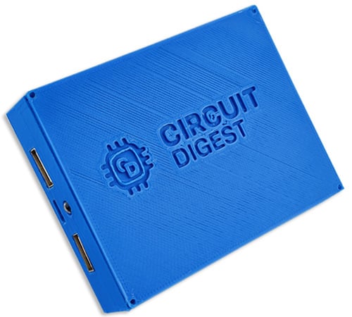
To safely keep all the circuitry enclosed, we designed an enclosure with all the cut-outs on Fusion-360 and 3D printed them.
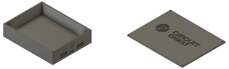
You ought to have a power bank that is securely sealed after putting everything together.
18650 Battery based Power Bank Circuit Working Explanation
This circuit's operation is rather straightforward. A DC power reservoir is provided by the 3.7V battery. Considering that the battery typically provides 3.7V DC. The charge controller module protects against overcharging while ensuring optimal charging. A consistent 5V/2A DC output is provided by the inbuilt DC to DC boost converter module found on the charger circuit board.
The onboard SMD LEDs on the charge control circuit board's bottom give charging-status signals when the circuit is linked to either an external output device or a wall outlet for charging.
Comments
Also, module doesn't seem to…
Also, module doesn't seem to be available in US.
Try serching for: Onyehn 3…
Try serching for:
Onyehn 3.7V Turn 5V 2A Boost Step Up Module Dual USB Charging Circuit Board PCB Board with Led Light for 18650 Lithium Battery Mobile Power Bank DIY 2 Pack
Very nice little project. Is…
Very nice little project. Is it possible to get the STL file please
How do you charge the…
How do you charge the batteries if they become depleted?
Sorry. I do see a mini USB…
Sorry. I do see a mini USB port on the power module. It was not clear in the photo.

Stl for the case?