

Nowadays we can’t even imagine a world without power. Even an intermittent power failure is so inconvenient. As we depend on electricity in many important areas of our life, it is important to take persuasion against power failures and that’s where the inverter plays an important role. There are multiple types of inverters in the market, such as square wave inverters, modified sine wave inverters, and pure sine wave inverters. The cheapest options would be square wave and modified sine wave inverters. But the difference between modified and pure sine wave inverters is that these types of inverters are not suitable for inductive loads such as motors, fans, etc. that’s where pure sine wave inverters come into play. They output a pure sinewave at line frequency so that it won’t affect such inductive loads.
So, in this project, we are going to build a pure sine wave inverter with a rating of 300W or 800VA. Let’s look at the components needed for this project.
Components Required
- EGS002 SPWM module
- IRF3205 N Channel MOSFETs
- 90N03 N Channel MOSFET
- LM7505 Voltage regulator
- FR207 Diodes
- S8050 Transistor
- 12V fan
- 10 Ohms resistors
- 1 KOhms resistor
- 1 KOhms resistor
- 10 KOhms NTC
- 10 KOhms Preset
- 0.1uF capacitors
- 2.2uF 650V Capacitor
- 10uF capacitors
- 2200uF capacitor
- 0-9V Transformer with a rating of 400W or higher
- Heat Sink
- Connectors
- Wires
- Copper Clad / Perfboard
- Soldering Kit
300W Pure Sine Wave Inverter Circuit Diagram
The complete circuit diagram for the Pure Sine Wave inverter is given below.

Now let’s have a look at each section.
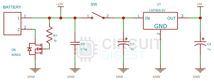
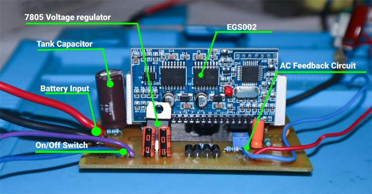
The power section consists of reverse polarity protection based on an N Channel MOSFET and an LM7805 voltage regulator along with some filter capacitors. The input from the battery is connected to the power input and then the positive is directly connected to a switch and the H-bridge. The negative is connected through an N Channel MOSFET for reverse polarity protection. LM7805 generates the necessary 5V for the EGS002 Module.
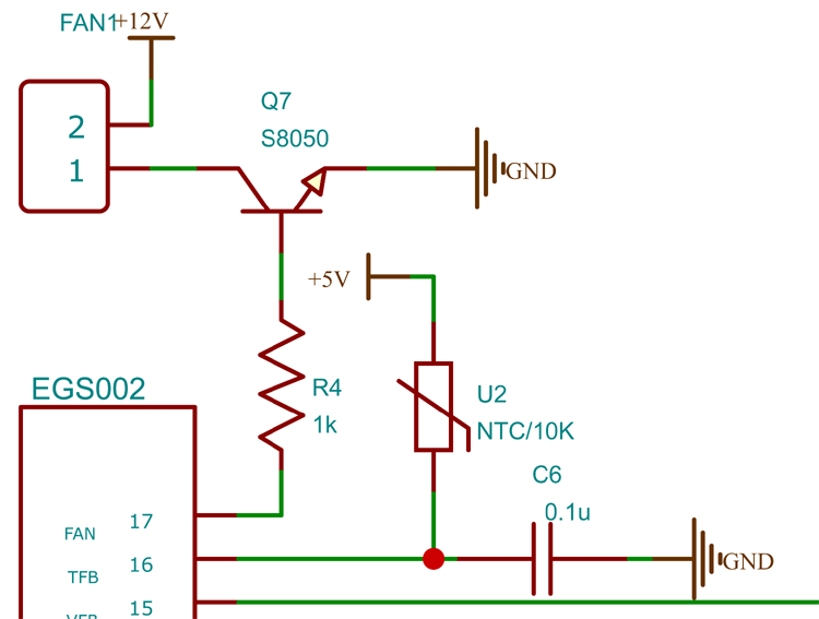
The temperature and fan control circuitry consists of a 10K NTC for temperature measurement and an NPN transistor to drive the fan. The temperature reading and the fan control are done by the EGS002 module itself.
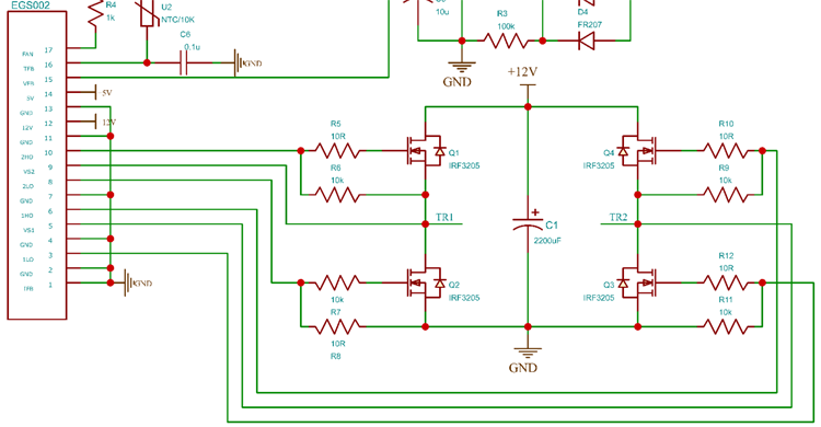
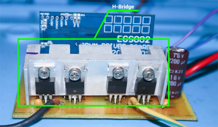
Next, the H-Bridge and EGS002 control circuit. The H-Bridge is made up of four IRF3205 MOSFETs. The control lines from the EGS002 are connected to the MOSFETs through the gate resistors. The transformer is connected to the points TR1 and TR2.
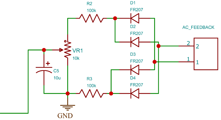
The feedback circuit consists of a bridge rectifier and a voltage divider. The variable resistor VR1 is used to adjust the output voltage by adjusting the feedback voltage. The AC voltage from the transformer is connected to the input of the bridge rectifier and the step-down voltage is connected to the VFB pin of the EGS002 module. The module will adjust the SPWM duty cycle with respect to this feedback voltage, to keep the output voltage stable.
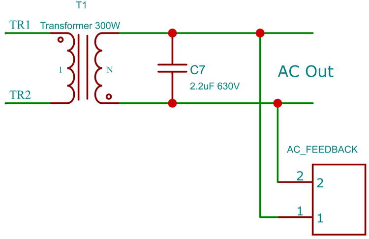
The transformer is connected to the H-Bridge at TR1 and TR2 points. In the output, a 2.2uF 650V capacitor is connected to filter out any high-frequency component from the SPWM. This filtered output is then connected to load and a feedback line of the EGS002.
Building and Testing the Pure Sine Wave Inverter Circuit
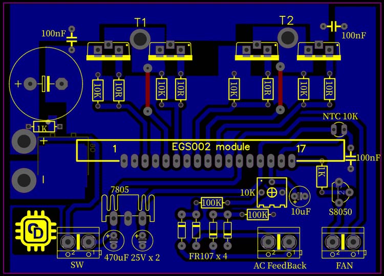
You can either build this project in a perfboard or you can make a PCB with the files from the link at the bottom of the page. Both PDF files for the toner transfer method and the Gerber file for the manufacturing are included. Here is the PCB layout for the inverter.
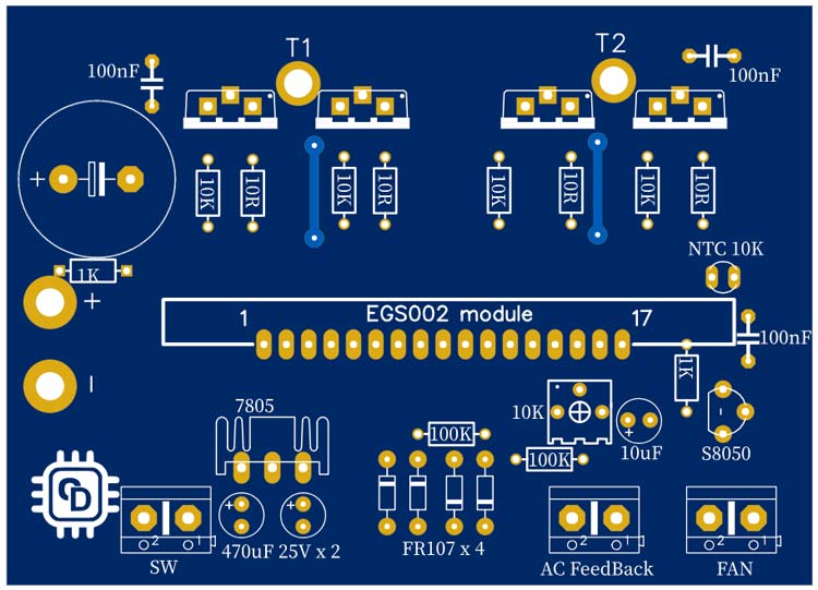
And here is the PCV view for the same.
Once you made the circuit with all appropriate connections, connect the battery and turn on the switch. If the inverter turns off after a few seconds with the LED on the EGS002 blinking three times, it is because the output voltage is not calibrated. Connect the output to a TrueRMS multimeter and adjust the variable resistor till the output voltage is set correctly.
Once the voltage is set the inverter will work without any errors. The EGS002 Module has a Low Voltage cut-off, so if the input voltage is reduced below minimum voltage the inverter will shut down automatically. Similarly, the module is featured with overcurrent protection and over-temperature protection. Let’s have a look at the EGS002 Module and its features.
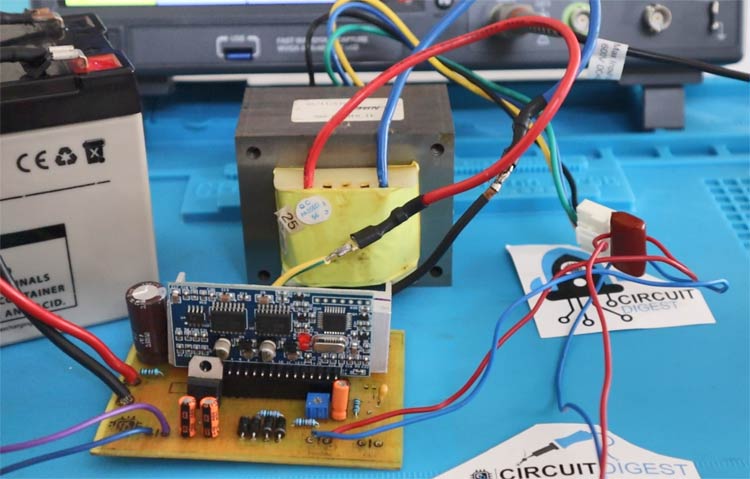
PCB And Main Components
Here is the PCB I have made, and the components used. You can see that the number of components is the bare minimum. The input is given through a high gauge wirer to reduce the voltage drop due to the resistance of the conductor. A tank capacitor of 2200uf is added to the input. The 5V for the EGS002 module is generated using the LM7805 voltage regulator and the filter capacitors. As already mentioned, the AC feedback circuit consists of a bridge diode made of four FR207 diodes, a voltage divider made of two 100KOhms resistors and a 10KOhms pre-set and a filter capacitor of value 10uF.
Here is the H-bridge circuit made of four N channel MOSFETs. You can use IRF3025 or any compatible ones for the H-Bridge circuit.
The below image shows the bottom side of the PCB. The bottom side only has one component. And that is an N-Channel MOSFET for the reverse polarity protection. The power traces are reinforced with solder for better current handling. All other traces are covered with solder to avoid the oxidisation on the home made PCB tracks.
EGS002 Module
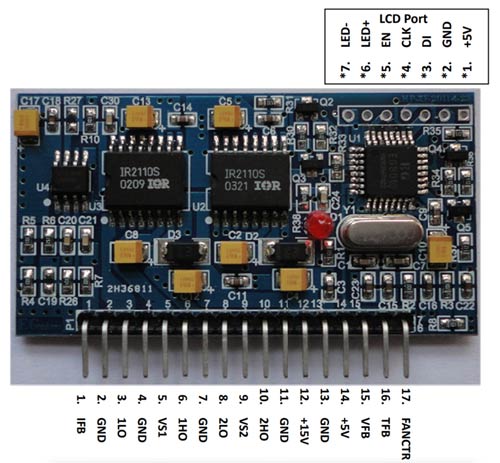
EGS002 is a driver board, designed for single-phase sinusoid inverters. It uses ASIC EG8010 as the control chip and IR2110S as the MOSFET driver chip. The driver board integrates functions of voltage, current and temperature protection, LED warning indication, and fan control. We can use jumpers to configure the following settings, Output frequency (50/60Hz), soft start mode, and dead time.
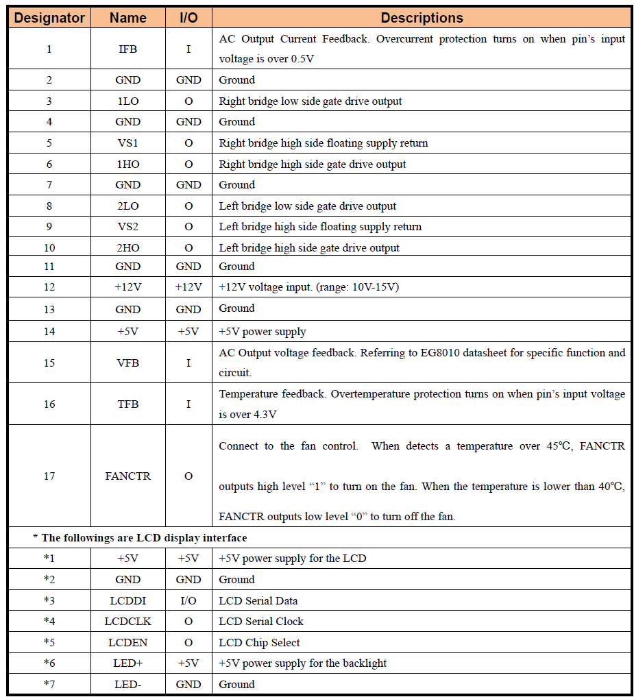
Here is the pin description table for the EGS002 module-
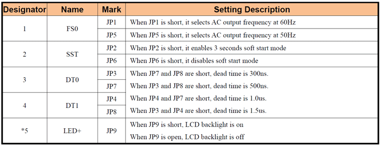
Jumper Configurations
As already mentioned, the EGS002 can be configured with the onboard jumpers. Let’s take a look at those. The following table shows the function of each of these jumpers.
LED Indications and Error Codes:
The EGS002 module can give error codes with the onboard LED. Here are the error codes and their meanings.
Normal: Lighting always on
Overcurrent: Blink twice, off for 2 seconds, and keep cycling
Overvoltage: Blink 3 times, off for 2 seconds, and keep cycling
Undervoltage: Blink 4 times, off for 2 seconds, and keep cycling
Overtemperature: Blink 5 times, off for 2 seconds, and keep cycling

Working of the 300W Pure Sinewave Inverter
The below gif shows the working of the pure sine wave inverter. The GIF showcases the soft start of the inverter.
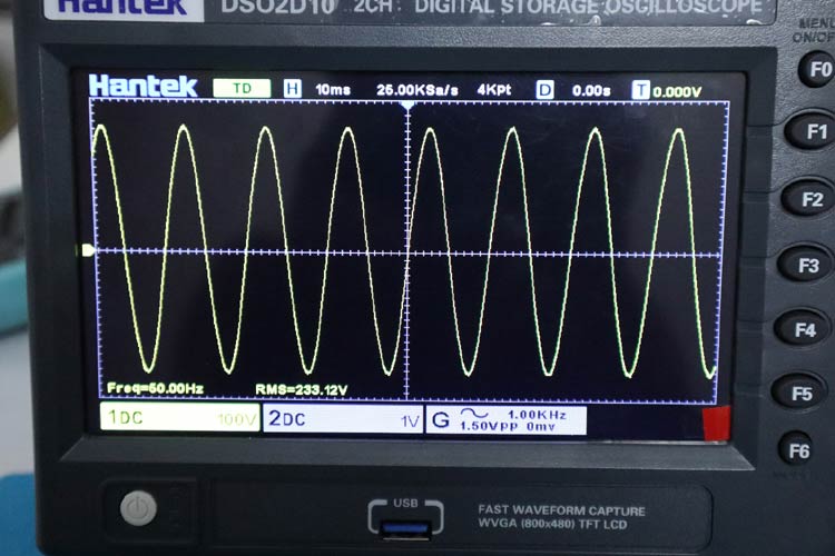
Here is the waveform view of the inverter output.
You can increase the inverter power by adding more MOSFETs and changing the transformer. All the files necessary to build this project can be found in the following GitHub repo.


Comments
Dear AVI Khalid, you can…
Dear AVI Khalid, you can find all the required files, including the Gerber file and the BOM in the following GitHub repo. https://github.com/Circuit-Digest/Pure-Sinewave-Inverter
Dear jobit Thank you the…
Dear jobit
Thank you the clear explanation in order to construct a 2Kw inverter can we use the same circuit except using bigger transformer and connecting more FET transistor in parallel appreciate showing me how to connect the power transistor
Kindest regards
Ihsan
Sir its found quite…
Sir its found quite Interesting.
I'm a VLE seek economical solutions to the power needs.
So seeking for DIY kit pl suggest or contact Wtsap 9356837273
hello sir, where did you put…
hello sir, where did you put the n channel 90n03 mosfet?
What should be the…
What should be the specification of the transformer used I.e the current rating
Please reply what should be…
Please reply what should be the current rating if the transformer used
I am very much interested in…
I am very much interested in learning and building the 300W Pure Sine Wave Inverter. Can I get a detailed video on how you did yours please
I am very much interested in…
I am very much interested in learning and building the 300W Pure Sine Wave Inverter. Can I get a detailed video on how you did yours please
Thanks for sharing the…
Thanks for sharing the EGS002 inverter project by Jobin Joseph. Unfortunately however, my circuit is cutting off indicating undervoltage when loaded with a 20W device. The source voltage drops to about 10.5V
I am testing a double conversion UPS inverter and so have a rectifier connected to the mains as a source for now. The Lion batteries had the same issue also.
I am supplying the inverter with 21V, have a feedback circuit, and have used precisely the exact components on the xls file together with the Gerber.
Please kindly assist on what could be the issue. Hope to here from you soon.
Cheers.
Please suggest me any…
Please suggest me any alternative of 90N03 N Channel MOSFET
We can replace it with any N…
We can replace it with any N Channel MOSFET such as IRFZ44, IRF3205 or p55, irf3205, irfp150n, irfp250n, irfp260n & so on.
Can you please confirm if…
Can you please confirm if the transformer will be 9v or 12v?
And if 9v then why 9v and not 12v
Thanks
Transformer should be the…
Transformer should be the UPS Transformer from old Ups.
The rating will be 7.5V to 220V transformer.
hello, please use the 6v to…
hello, please use the 6v to 230v transformer. i have used the same.
at present i'm getting around 400-500w using 4mosfet, question is can i achive 1500w using more mosfet in paralell and higher amp rating transformer??
Yes, you can achieve higher…
Yes, you can achieve higher wattage by increasing the number of MOSFETs and by using a transformer with higher wattage. Make sure to strengthen the high-current tracks with think copper wires and solder. Also, the reverse polarity protection circuit also needs to be modified to handle the high current.


Hi Jobit,
I am very much interested in learning and building the 300W Pure Sine Wave Inverter. Regarding the components list is there a way to specify how many components are needed. Example how many IRF 3205N Channel MOSFET’s how many 90N03 N Channel MOSFET, so on is it possible to provide the info to make it easier to organize The and order BOM (Bill of Materials) also if you have the schematics in a Gerber file if we decided to order a professionally made PCB
Thanks.
Avi