

Today, our desks are full of devices that require to be connected with the PC via USB or we need to work with multiple things that are having USB. It became a problem as Laptops lack multiple ports and this is where a USB hub or USB Port Extender comes in handy.
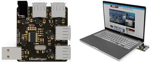
A USB hub is a useful device that provides the flexibility to turn a single Universal Serial Bus (USB) port into a multi port system so we can connect more devices to a host system. In a multi-port USB HUB system, we can use multiple USB devices such as a mouse, keyboard, pen drives, and others, and the bandwidth of the host USB is shared among them. In this project, we will discuss how to design a USB Hub, that can help you in extending one USB port into four. Along the way, we will also learn how to implement USB Input/Output protection circuits and how to design a PCB for the same.
The USB hub PCB boards built in this project were fabricated by our long-time sponsor pcbway.com. For those who are new, PCBWay is a Fabrication and Assembly service provider that can provide high quality, full-featured custom PCBs for prototype and manufacturing quantities. We will discuss more on how to use their services later, but if you want to get your hands on these USB hubs PCB boards you can also check out the Project Giveaway! which is explained in the video linked at the bottom of this page.
Specification of the USB Hub:
- USB2.0 Facility
- 4 Dedicated Port.
- Self Power and External Power Option
The USB Hub will support the USB2.0 facility and will have 4 Dedicated USB Ports. It can be self-powered, meaning it will take power from the Host USB Port and distribute it to other connected USB devices or an external 5V power source will allow it to power the external devices.
Components Required for Building a DIY USB Hub
|
Qty |
Value |
Package |
Parts |
|
12 |
0.1uF |
C0603 |
C5, C6, C7, C8, C11, C12, C13, C15, C17, C18, C20, C21 |
|
1 |
100k |
R0805 |
R11 |
|
5 |
100uF |
E2-5 |
C1, C2, C3, C4, C22 |
|
1 |
10k |
R0603 |
R8 |
|
1 |
10k |
R0805 |
R6 |
|
1 |
10uF |
E2-5 |
C19 |
|
1 |
12MHz |
XTAL_ECS-120-18-4X-CKM |
Y1 |
|
2 |
1uF |
C0603 |
C14, C16 |
|
1 |
2.5A/30V/105mΩ |
SOT23-3 |
Q1 |
|
1 |
20k |
R0805 |
R7 |
|
2 |
33pF |
C0603 |
C9, C10 |
|
1 |
4.7k |
R0805 |
R12 |
|
1 |
470R |
R0805 |
R10 |
|
1 |
470k |
R0805 |
R13 |
|
1 |
47k |
R0603 |
R9 |
|
4 |
500mA |
THRMC2012X50N |
R1, R2, R3, R4 |
|
1 |
680R |
R0603 |
R5 |
|
1 |
DC-Socket |
DCJACK_2MM_PTH |
CN1 |
|
6 |
FB-0603-2A |
INDC1608X95N |
L1, L2, L3, L4, L5, L6 |
|
1 |
GL850G-HH |
SOP65P780X200-2N |
IC1 |
|
1 |
RED |
CHIPLED_0805 |
LED1 |
|
3 |
SRV05-4 - ESD Protection |
SOT95P280X145-6N |
IC2, IC3, IC4 |
|
4 |
USB-A-S-X-X-TH |
SAMTEC_USB-A-S-X-X-TH |
J1, J2, J3, J4 |
|
1 |
USB-AM-S-X-X-TH |
SAMTEC_USB-AM-S-X-X-TH |
J5 |
The Bill of materials is having the component designator on PCB. For the Schematic and the PCB, let's move to the next section -
DIY USB Hub Circuit Diagram
The complete schematic for DIY USB Hub is given below:

Let's see how the components are connected. For better understanding, each section of the schematic is separated as a block as per the working principle of each major component.
GL850G Controller Section:
GL850G is the main IC of this application. It is from Genesys Logic’s advanced version Hub solutions which fully comply with Universal Serial Bus Specification Revision 2.0.
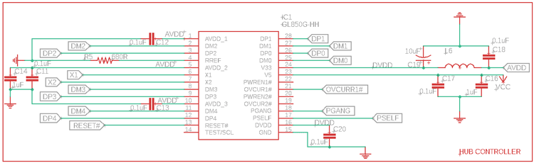
We have chosen this as it provides major advantages during the design process of USB HUB.
It has both 5V to 3.3V and 3.3V to 1.8V voltage drop regulators into a single chip, therefore external LDOs are not required and the cost can be saved.
As a brief description, GL850G uses an 8-bit RISC processor to manipulate the control/status registers and respond to the requests from the USB host. GL850G is also having pre-installed firmware that will control its general purpose I/O and also access the external EEPROM.
In the above schematic, we are using the 4 downstream ports connected as DP1, DM1, DP2, DM2, and so on, up to DP4, DM4. This is the main USB D+ and D- a connection that goes to the respective USB devices.
It is taking power through pin 25, which is a 5V line, and pin 24 which is a 3.3V pin. The 3.3V section has a PI filter 0.1uF and 10uF capacitor and a ferrite bead to provide a clean supply as an analog voltage.
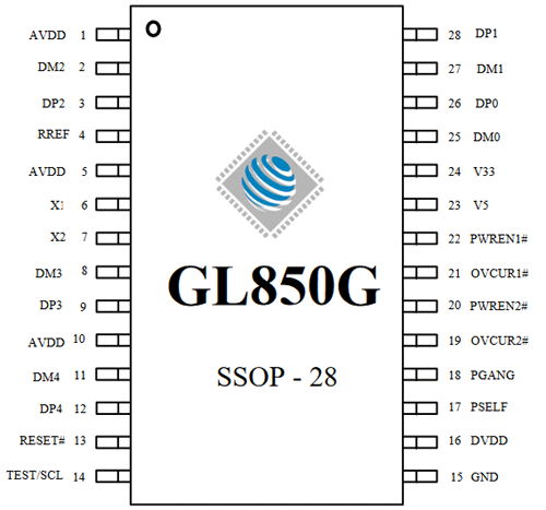
The pinout can be seen in the below-
USB Host connection and Overcurrent section:
This is the Input of the USB. It is having a male USB socket that will be inserted into the PC, Laptop, or device that is having the USB HUB Feature. There is also an ESD protection being used, having the IC4 which will protect this upstream port from ESD.
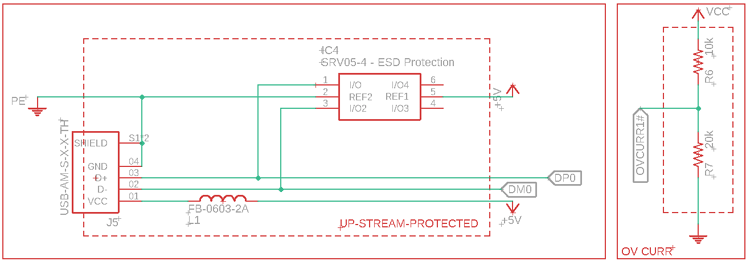
The overcurrent voltage divider is used to bias the overcurrent pin. The voltage divider is set to provide 3.3V at this pin to activate the overcurrent protection feature for the USB BUS on 4 ports.
4x Downstream port:
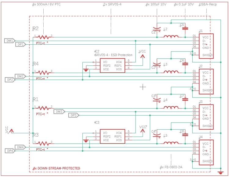
In the above image, 4 downstream ports are shown. All are using individual filters in the power line for providing clean power on the USB devices. However, there are 4 PTC available for protecting high current drives.
Other than that, IC2 and IC3 is the TVS diode to protect the internal devices from the ESD surges.
Peripheral Circuit:
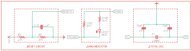
The first one is the Reset Circuit. This is a simple voltage divider for reset which has a voltage output of 4V. So, when the 5V goes low, it could change the threshold voltage of the GL850G reset.
The middle one is the GANG indicator. When 4 USBs are active this Indicator will be turned on.
The last one is the 12Mhz crystal oscillator, used by the GL850G.
External Power provision and logic:
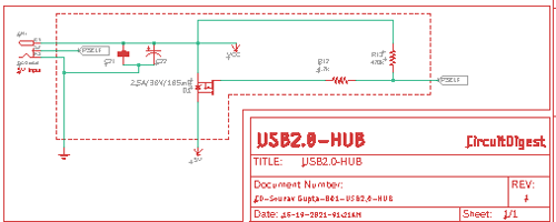
In the above circuit, a MOSFET is controlled using the Battery connector Logic. At normal conditions, the MOSFET gets turned off, but when someone inserts a connector, the DC barrel connector switch gets disconnected and the power of 5V gets connected with the supply rail via the MOSFET.
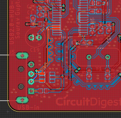
Fabricating the PCB for USB Hub
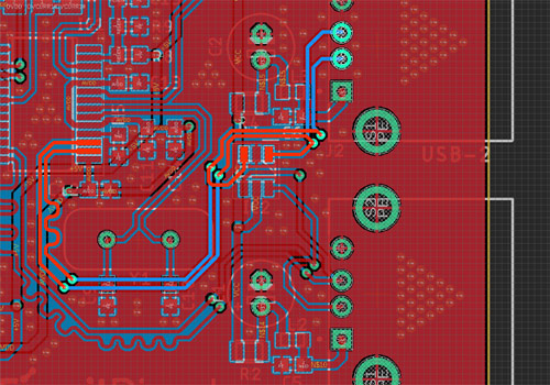
The PCB is designed properly with proper differential pair terminations. Important traces are shown below where the USB differential pair lengths are matched. If you are new to differential routing in PCB design, you can check this article that explains the importance of differential pair routing and how to use it.
The below section is the Input USB.
This is the USB 1 trace.
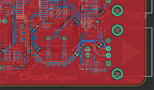
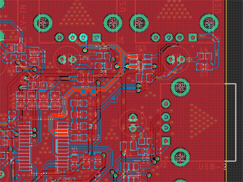
This is the USB 2 trace.
This is the USB 3 trace.
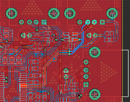
This is the USB 4 trace.
This is the Whole PCB
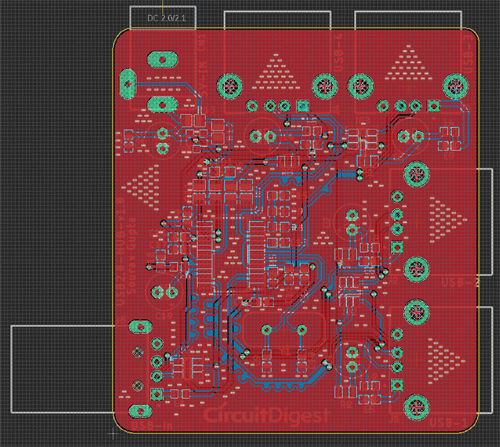
The PCB is converted to the 3D before making the design -
Ordering PCB from PCBWay
Now after finalizing the design, you can proceed with ordering the PCB:
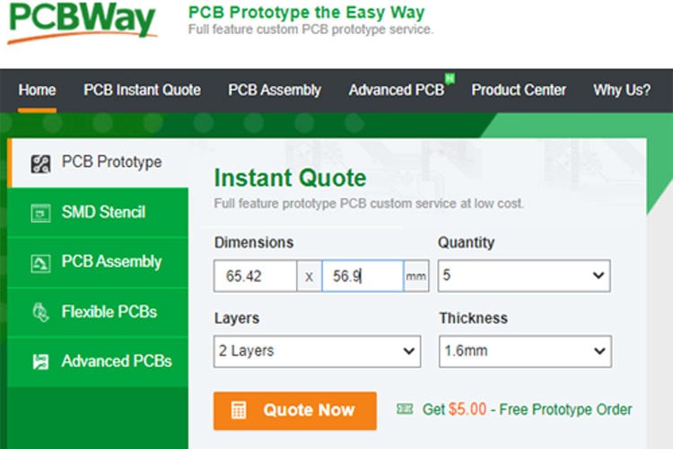
Step 1: Get into https://www.pcbway.com/, sign up if this is your first time. Then, in the PCB Prototype tab, enter the dimensions of your PCB, the number of layers, and the number of PCBs you require.
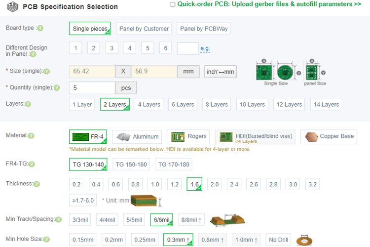
Step 2: Proceed by clicking on the ‘Quote Now’ button. You will be taken to a page where to set a few additional parameters like the Board type, Layers, Material for PCB, Thickness, and More, most of them are selected by default, if you are opting for any specific parameters, you can select it in here.
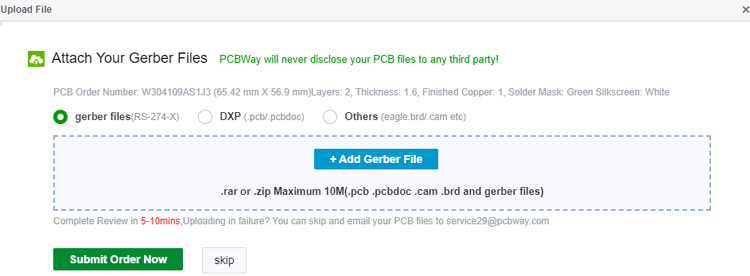
Step 3: The final step is to upload the Gerber file and proceed with the payment. To make sure the process is smooth, PCBWAY verifies if your Gerber file is valid before proceeding with the payment. This way, you can be sure that your PCB is fabrication friendly and will reach you as committed.
Assembling the PCB
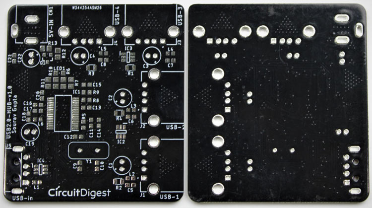
After the board was ordered, it reached me after some days through courier in a neatly labeled well-packed box. The PCB quality was good as always. The top layer and the bottom layer of the board are shown below:
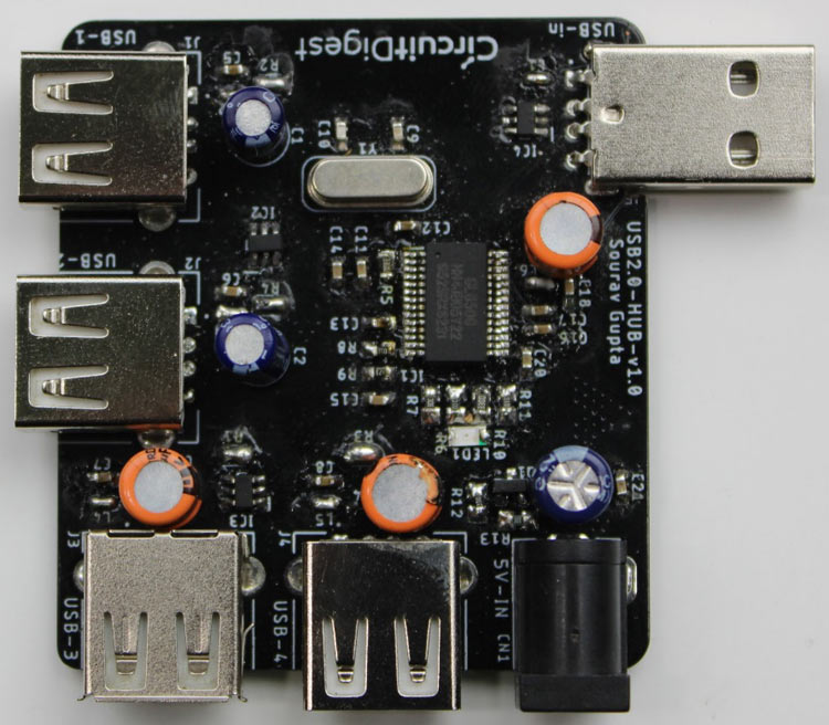
After making sure the tracks and footprints were correct. I proceeded with the assembling of the PCB. The completely soldered board looks like the below:
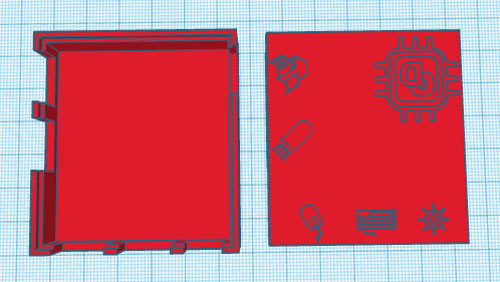
3-D Printing the Casing for USB Port Extender
After assembling the PCB and making sure that everything is fine, I printed a casing for the PCB. For that, I measured the dimensions of the board, all the USB ports, and barrel jack to design a casing for my setup. My design looked something like this below once it was done.
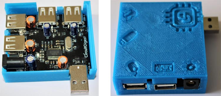
After I was satisfied with the design, I exported it as an STL file, sliced it based on printer settings, and finally printed it. The STL file is also available for download from Thingiverse and you can print your own casing using it.
After the print was done, I proceeded with assembling the project set-up in a permanent enclosure for future use and everything was nicely fit as you can see below:
Testing the USB Hub
After assembling the PCB and fixing the PCB inside a 3-D printed enclosure, I plugged this into one of my Laptop’s USB ports and then connected 4 USB devices to its USB ports. All the four devices connected to this USB Hub were working seamlessly.
The complete working for this project can be found in the video below, if you have any questions, you can leave them in the comment section below or you can also use our forums.
Comments
Great project. Where are the
Great project. Where are the fieles to download please?? Thank you
What are the ohm values for…
Design and BOM need more details....
What are the ohm values for the ferrite beads used in this project? The same question for the thermistors used Can you provide more detail about the crystal used such as pf value.
Can you please provide more…
Can you please provide more detail as to how to find the exact thermistors needed for this project please?

Are you releasing the Gerber files for this project?
If I have missed them in the article can you identify where I can find them.
Thanks
Ray Drury