
A superheterodyne receiver uses signal mixing to convert the input radio signal into a steady intermediate frequency (IF) that can be worked with more easily than the original radio signal that has a different frequency, depending on the broadcasting station. The IF signal is then amplified by a strip of IF amplifiers and then fed into a detector that outputs the audio signal into an audio amplifier that powers the speaker. In this article, we will learn about the working of a Superheterodyne AM receiver or superhet for short with the help of a block diagram.
Most AM receivers found today are of superheterodyne type because they allow for the use of high selectivity filters in their Intermediate Frequency (IF) stages and they have high sensitivity (internal ferrite rod antennas can be used) due to the filters in the IF stage which helps them in getting rid of unwanted RF signals. Also, the IF amplifier strip providing high gain, good strong signal response because of the use of automatic gain control in amplifiers and ease of operation (only controls volume, power switch, and the tuning knob).
Block Diagram of Superheterodyne AM Receiver
To understand how it works, let’s take a look at the Superheterodyne AM Receiver Block Diagram which is shown below.
As you can see the block diagram has 11 different stages, each stage has a specific function which is explained below
- RF Filter: The first block is the ferrite rod antenna coil and variable capacitor combo, that serves two purposes - RF is induced into the coil and the parallel capacitor controls the resonant frequency of it, as ferrite antennas receive the best when the resonant frequency of the coil and capacitor is equal to the station's carrier frequency – this way it acts as an input filter of the receiver.
- Heterodyne Local Oscillator: The second block is the heterodyne, also known as the local oscillator (LO). The frequency of the local oscillator is set, so either the sum or the difference of the RF signal’s frequency and the LO’s frequency is equal to the IF used in the receiver (usually around 455 kHz).
- Mixer: The third block is the mixer, the RF signal and the LO signal is fed to the mixer to produce the desired IF. Mixers found in common AM receivers output the sum, the difference of the LO and RF’s frequencies and the LO and RF signals themselves. Most often in simple transistor radios, the heterodyne and the mixer are made using one transistor. In higher-quality receivers and those that use dedicated integrated circuits, such as the TCA440, these stages are separate, allowing for more sensitive reception due to the mixer outputting only the sum and difference frequencies. In one transistor LO-mixers, the transistor operates as a common-base Armstrong oscillator and the RF taken from a coil wound on the ferrite rod, separate from the resonant circuit’s coil, is fed to the base. At frequencies different from the resonant frequency of the antenna resonant circuit, it presents low impedance, so the base stays grounded for the LO signal but not for the input signal, due to the antenna circuit being of parallel resonant type (low impedance at frequencies different from resonance, almost infinite impedance at the resonant frequency).
- First IF Filter: The fourth block is the first IF filter. In most AM receivers, it is a resonant circuit placed in the collector of the mixer transistor with the resonant frequency equal to the IF frequency. Its purpose is to filter off all signals with a frequency different from the IF frequency because those signals are unwanted mixing products and don’t carry the audio signal of the station we want to listen to.
- First IF Amplifier: The fifth block is the first IF amplifier. Gains of 50 to 100 in each IF stages are common if the gain is too high, distortion can take place, and if the gain is too high, IF filters are too close to each other and not properly shielded, parasitic oscillation can take place. The amplifier is controlled by AGC (Automatic Gain Control) voltage from the demodulator. AGC lowers the gain of the stage, causing the output signal to be roughly the same, regardless of the input signal amplitude. In transistor AM receivers, the AGC signal is most often fed to the base and has a negative voltage – in NPN transistors pulling the base bias voltage lower, reduces gain.
- Second IF Filter: The sixth block is the second IF filter, just like the first one it is a resonant circuit placed in the collector of the transistor. It only lets signals of the IF frequency – improving selectivity.
- Second IF Amplifier: The seventh block is the second IF amplifier, it is practically the same as the first IF amp except it is not controlled by AGC, as having too many AGC controlled stages, increases distortion.
- Third IF Filter: the eighth block is the third IF filter, just like the first and the second one is a resonant circuit placed in the collector of the transistor. It only lets signals of the IF frequency – improving selectivity. It feeds the IF signal to the detector.
- Detector: The ninth block is the detector, usually in the form of a germanium diode or a diode-connected transistor. It demodulates AM by rectifying the IF. On its output, there is a strong IF ripple component that is filtered out by a resistor-capacitor low pass filter, so only AF component remains, it is fed to the audio amp. The audio signal is further filtered to provide the AGC voltage, like in a regular DC power supply.
- Audio Amplifier: The tenth block is the audio amplifier; it amplifies the audio signal and passes it onto the speaker. Between the detector and the audio amplifier, a volume control potentiometer is used.
- Speaker: The last block is the speaker (usually 8 ohms, 0.5W) that outputs audio to the user. The speaker is sometimes connected to the audio amplifier through a headphone jack that disconnects the speaker when headphones are plugged in.
Superheterodyne AM Receiver Circuit
Now, we know the basic functionality working of a Superheterodyne Receiver, let’s take a look at a typical circuit diagram of Superheterodyne Receiver. The below circuit is an example of a simple transistor radio circuit constructed using TR830 super sensitive transistor from Sony.

The circuit might appear complicated on the first look, but if we compare it with the block diagram that we learned earlier, it becomes simple. So, let’s split each section of the circuit to explain its working.
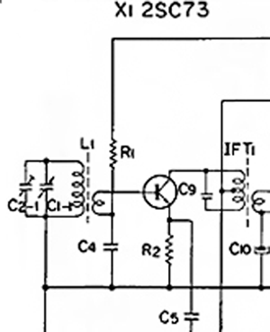
Antenna and mixer – L1 is the ferrite rod antenna, it forms a resonant circuit with C2-1 and C1-1 variable capacitor in parallel. The secondary winding couples into the base of mixer transistor X1. The LO signal is fed to the emitter from the LO by C5. Output IF is taken from the collector by IFT1, the coil is tapped on the collector in an auto-transformer fashion, because if the resonant circuit was connected directly between the collector and Vcc the transistor would load the circuit considerably and the bandwidth would be too high – around 200kHz. This tapping reduces bandwidth to 30kHz.
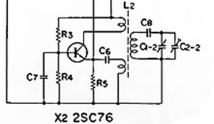
LO – Standard common-base Armstrong oscillator, C1-2 is tuned alongside C1-1 in order that the difference of the LO and RF frequencies is always 455kHz. The LO frequency is determined by L2 and the total capacitance of C1-2 and C2-2 in series with C8. L2 provides feedback for oscillations from the collector to the emitter. The base is RF grounded.
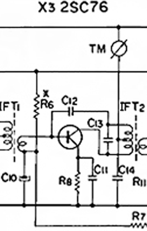
X3 is the first IF amp. To use a transformer to feed the base of a transistor amplifier, we put the secondary between the base and the bias and put a decoupling capacitor between bias and transformer secondary to close the circuit for the signal. This is a more efficient solution than feeding the signal through a coupling capacitor to the base connected directly to bias resistors
TM is a signal strength meter measuring current flowing into the IF amp, as higher input signals cause more current to flow through the IF transformer into the second IF amp, increasing IF amp supply current that the meter measures. C14 filters the supply voltage along with R9 (off-screen), as RF and electric grid hum can be induced into the coil of TM meter.
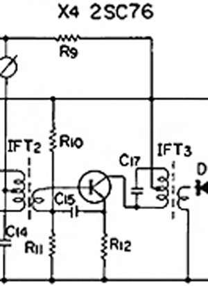
X4 is the second IF amp, bias is fixed set by R10 and R11, C15 ground the base for IF signals; it’s connected to the un-decoupled R12 to provide negative feedback in order to decrease distortion, all else is the same as in the first amp.
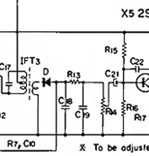
D is the detector. It demodulates the IF and supplies the negative AGC voltage. Germanium diodes are used, because of their forward voltage being two times lower than silicon diodes, causing higher receiver sensitivity and lower audio distortion/ R13, C18 and C19 form a PI topology low-pass audio filter, while R7 controls AGC strength and forms a low-pass filter with C10 that filters the AGC voltage from both the IF and the AF signal.
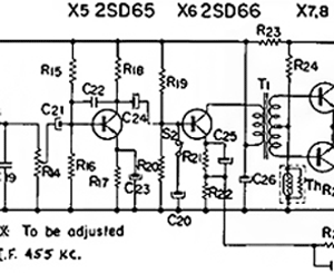
X5 is the audio preamplifier, R4 controls volume and C22 provides negative feedback at higher frequencies, providing additional low-pass filtering. X6 is the driver of the power stage. S2 and C20 form a tone control circuit – when the switch is pressed C20 grounds higher audio frequencies, acting as a crude low-pass filter, this was important in early AM radios, as speakers had very bad low frequency performance and received audio sounded “tinny”. Negative feedback from the output is applied to the emitter circuit of the driver transistor.
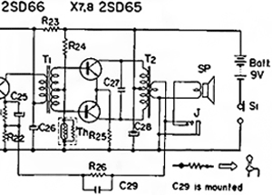
T1 inverts the phase of signals coming to the base of X7 versus the phase at base of X8, T2 turns the half-wave current pulls of each transistor back to a whole waveform and matches the higher transistor amp impedance (200 ohms) to the 8-ohm speaker. One transistor pulls current when the input signal is at waveform positive and the other one when the waveform is negative. R26 and C29 provide negative feedback, reducing distortion and improving audio quality and frequency response. J and SP are connected in a way that switches the speaker off when headphones are plugged in. The audio amp provides around 100mW of power, sufficient for an entire room.

Midterm Exam:
Using a pencil and ruler, illustrate manually and explain the following circuits:
• Superheterodyne AM Receiver
• Block diagram of a typical transistor AM superheterodyne receiver
• Simple transistor radio circuit (model TR-830)
• Antenna and mixer