
Detection of air flow is useful in many projects and applications. Here we are building a very simple circuit to detect the air flow presence. This circuit doesn’t require any fancy stuff like Resistance Temperature Detector (RTD) or Zener diode etc. Here we are using a simple AC bulb filament with some cheap component to detect the air. This is very interesting project using very fewer components and all the components are easily available for this project.
Components Required:
- LM358 Dual Op-Amp IC
- LM7805 Voltage Regulator
- Bread Board
- Resistor 100ohm, 680ohm, 330ohm, 10K
- 50k variable Resistor
- LED
- Capacitor 100uF
- Jumper wire
- Incandescent Bulb
- Power Supply 12v
- Push button (Optional)
- DC Fan (Optional)
Circuit Diagram and Explanation:
Below is the schematic diagram for Air Flow Detection Circuit:

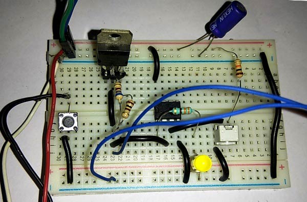
This circuit is a visual indication of airflow. We can detect the air presence or air flow by using this circuit. The main component of this air flow sensor circuit is bulb filament which is responsible for creating variation in voltage when there is airflow. Bulb filament has the negative temperature coefficient and because of that its filament resistance change inversely to the temperature. Like when temperature is high, filament resistance will be low and vice versa.
So by default when there is no air, then resistance value of bulb filament is low because of some heat in it. Now whenever any air flow passes from it, the heat or temperature of the bulb filament reduces and the resistance of filament increases. And due to this change in resistance, a voltage difference generates across the bulb filament. This voltage difference is caught by Op-amp LM358 and it generates a low signal. Op-amp is configured in comparator mode, which compares input voltage with the reference voltage and gives the output accordingly. Check here for more op-amp circuits and LM358 circuits.
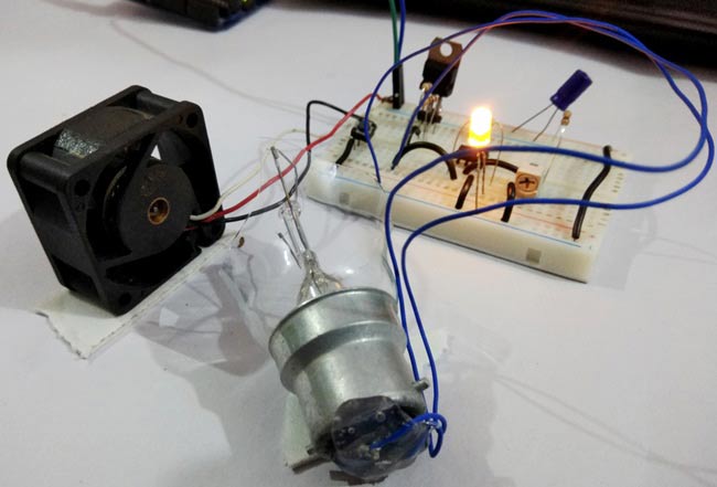
A Potentiometer is used for calibrating the circuit. An LED is used for indication of airflow. A push button and a DC fan are used to flow the air through the filament. User may also flow air by his mouth. This whole circuit is powered by using 12v DC supply.
Check the Video Below for Demonstration.
Comments
Computation of values.
Can you show me how you solve each values? I really want to dig dipper in this subject and would like to know the basics in identifying the values to use. Thank you so much. This would really be a great help to me. :D
Juan, simulate the circuit to
Juan, simulate the circuit to understand it much better
Awesome .....but how to get
Awesome .....but how to get resistor values ....design ??????
Great circuit.. it will be a
Great circuit.. it will be a great help if you can you tell me where did you use 12V supply as i see, you only took 5V supply from arduino?

This is a good design.