

Almost every Solar based system has a Battery associated with it which has to be charged from solar energy and then the energy from the battery will be used to drive the loads. There are multiple choices available for charging a lithium battery, we have also built a simple Lithium battery charging circuit previously. But to charge a battery with a solar panel, the most popular choice is the MPPT or maximum power point tracker topology because it provides much better accuracy than other methods like PWM controlled chargers.
MPPT is an algorithm commonly used in solar chargers. The charge controller measures the output voltage from the panels and the battery voltage, then by getting these two data, it compares them to decide the best power that the panel could provide to charge the battery. At whatever the situation, whether in good or poor sunlight condition, the MPPT charge controller uses this maximum power output factor and converts this to the best charge voltage and current for the battery. Whenever the power output from the solar panel gets dropped, the battery charge current also decreases.
Thus, in poor sunlight conditions, the battery continuously gets charged according to the output of the solar panel. This is usually not the case in normal solar chargers. Because each solar panels comes with a maximum output current rating and a short circuit current rating. Whenever the solar panel could not provide the proper current output, the voltage falls significantly and the load current does not change and crosses the short circuit current rating making the output voltage of the solar panel is zero. Hence, the charging gets stopped completely in poor sunlight conditions. But MPPT allows the battery to charge even in the poor sunlight condition by controlling the battery charge current.
MPPTs are around 90-95% efficient in the conversion. However, efficiency is also dependable on the solar driver temperature, battery temperature, solar panel quality, and conversion efficiency. In this project, we will build a Solar MPPT charger for lithium batteries and check the output. You can also check out the IoT Based Solar battery monitoring Project in which we monitoring some critical battery parameters of a lithium battery installed in a Solar System.
MPPT Charge Controller - Design Considerations
The MPPT Charge controller circuit that we design in this project will have the following specifications meat.
- It will charge a 2P2S battery (6.4-8.4V)
- Charge current will be 600mA
- It will have an additional charging option using an adapter.
Components Required for Building MPPT Controller
- LT3652 Driver
- 1N5819 - 3 pcs
- 10k pot
- 10uF Capacitors - 2 pcs
- Green LED
- Orange LED
- 220k resistor
- 330k resistor
- 200k resistor
- 68uH Inductor
- 1uF capacitor
- 100uF capacitor - 2 pcs
- Battery - 7.4V
- 1k resistors 2 pcs
- Barrel socket
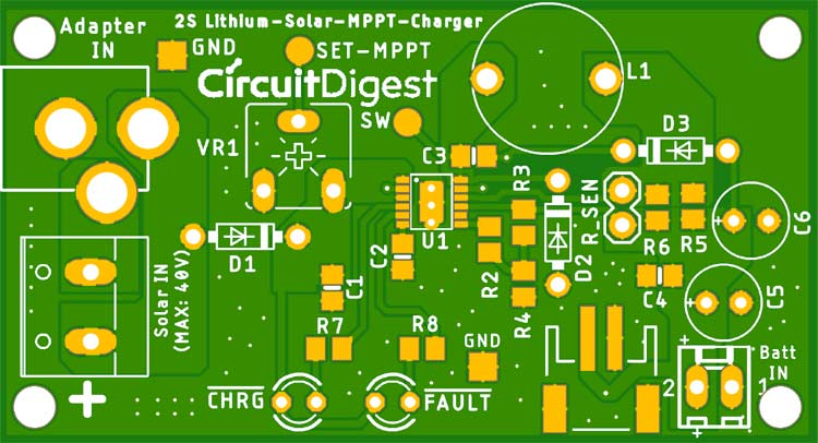
MPPT Solar Charger Circuit Diagram
The complete Solar Charge Controller Circuit can be found in the image below. You can click on it for a full-page view to get better visibility.

The circuit uses LT3652 which is a complete monolithic step-down battery charger that operates over a 4.95V to 32V input voltage range. Thus, the maximum input range is 4.95V to the 32V for both solar and adapter. The LT3652 provides a constant current / constant voltage charge characteristics. It can be programmed through current sense resistors for a maximum of 2A charge current.
On the output section, the charger employs 3.3V float voltage feedback reference, so any desired battery float voltage up to 14.4V can be programmed with a resistor divider. The LT3652 also contains a programmable safety timer using a simple capacitor. It is used for charge termination after the desired time is reached. It is useful to detect battery faults.
The LT3652 requires MPPT setup where a potentiometer can be used to set the MPPT point. When the LT3652 is powered using a solar panel, the input regulation loop is used to maintain the panel at peak output power. From where the regulation is maintained depends on the MPPT setup potentiometer.
All these things are connected to the schematic. The VR1 is used to set the MPPT point. R2, R3, and R4 are used to set the 2S battery charging voltage (8.4V). Formula to set battery voltage can be given by-
RFB1 = (VBAT(FLT) • 2.5 • 105)/3.3 and RFB2 = (RFB1 • (2.5 • 105))/(RFB1 - (2.5 • 105))
The capacitor C2 is used to set up the charge timer. The timer can be set using the below formula-
tEOC = CTIMER • 4.4 • 106 (In Hours)
The D3 and C3 are the boost diode and boost capacitor. It drives the internal switch and facilitates the saturation of the switch transistor. The boost pin operates from 0V to 8.5V.
R5 and R6 are a current sense resistor connected in parallel. The charge current can be calculated using the below formula-
RSENSE = 0.1/ ICHG(MAX)
The current sense resistor in the schematic is selected 0.5 Ohms and 0.22 Ohms which is in parallel creates 0.15 Ohms. Using the above formula, it will produce almost 0.66A of charge current. The C4, C5, and C6 are the output filter capacitors.
The DC barrel jack is connected in such a way that the solar panel will get disconnected if an adapter jack is inserted into the adapter socket. The D1 will protect the solar panel or the adapter from reverse current flow during no charging condition.
Solar Charge Controller PCB Design
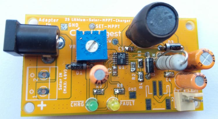
For the above discussed MMPT circuit, we designed the MPPT charger controller circuit board that is shown below.
The design has the necessary GND copper plane as well as proper connecting vias. However, the LT3652 requires adequate PCB heat sink. This is created using the GND copper plane and placing vias in that solder plane.
Ordering the PCB
Now we understand how the schematics work, we can proceed with building the PCB for our MPPT Solar Charger Project. The PCB layout for the above circuit is also available for download as Gerber from the link.
Now our design is ready, it is time to get them fabricated using the Gerber file. To get the PCB done from PCBGOGO is quite easy, simply follow the steps below-
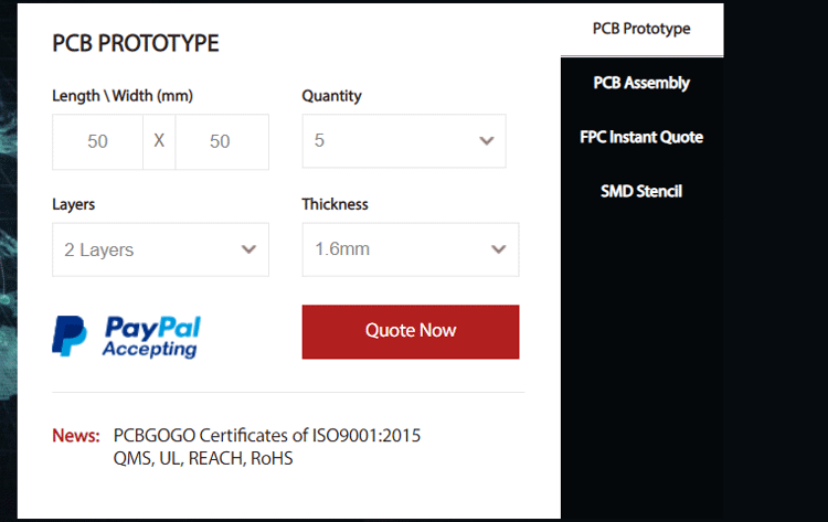
Step 1: Get into www.pcbgogo.com, sign up if this is your first time. Then in the PCB Prototype tab, enter the dimensions of your PCB, the number of layers, and the number of PCB you require. Assuming the PCB is 80cm×80cm, you can set the dimensions as shown below.
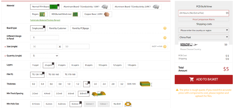
Step 2: Proceed by clicking on the Quote Now button. You will be taken to a page where to set a few additional parameters if required like the material used track spacing, etc. But mostly, the default values will work fine. The only thing that we have to consider here is the price and time. As you can see the Build Time is only 2-3 days and it just costs only $5 for our PCB. You can then select a preferred shipping method based on your requirement.
Step 3: The final step is to upload the Gerber file and proceed with the payment. To make sure the process is smooth, PCBGOGO verifies if your Gerber file is valid before proceeding with the payment. This way, you can sure that your PCB is fabrication friendly and will reach you as committed.

Assembling the PCB
After the board was ordered, it reached me after some days through courier in a neatly labeled well-packed box, and like always, the quality of the PCB was awesome. The PCB that was received by me is shown below. As you see, both the top and bottom layer has turned out as expected.
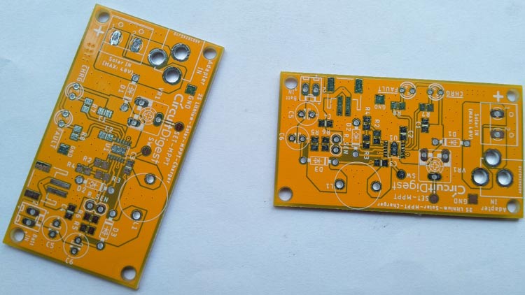
The vias and pads were all in the right size. It took me around 15 minutes to assemble to PCB board to get a working circuit. The assembled board is shown below.
Testing our MPPT Solar Charger
To test the circuit, a solar panel with 18V .56A of rating is used. The below image is the detailed specification of the solar panel.
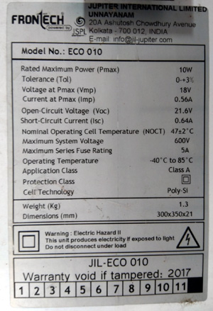
A 2P2S battery (8.4V 4000mAH) battery is used for charging. The complete circuit is tested in moderate sun condition–
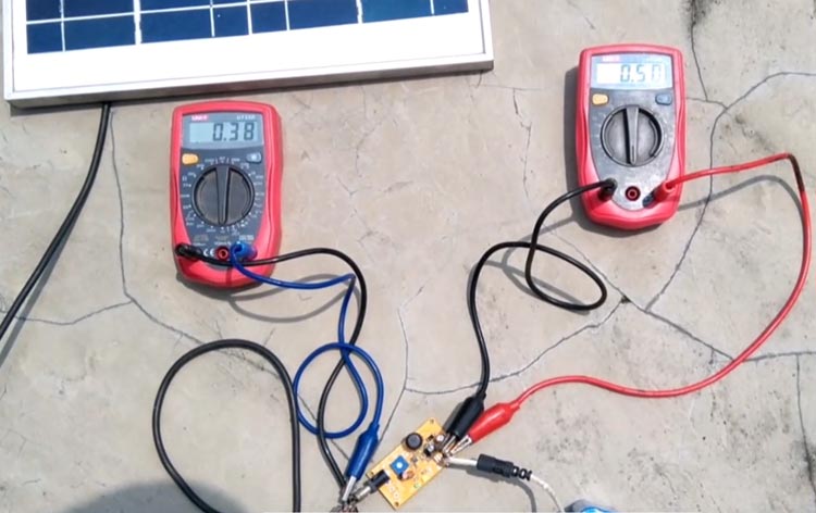
After connecting everything, the MPPT is set when the Sun condition is proper and the potentiometer is controlled until the charge LED starts to glow. The circuit worked pretty well and the detailed working, setup, and explanation can be found in the video linked below.
Hope you enjoyed the project and learned something useful. If you have any questions, please leave them in the comment section below. You can also use our forums to get your other technical queries answered.
Comments
I think you have a glitch in
I think you have a glitch in your title.
It's a LT 3652 and not a LT 3562.
Regards.
Laszlo
sir,please share vdieo of…
sir,please share vdieo of how to design mppt solar charge controller
how to i order to pcb design…
how to i order to pcb design ? Please give me your email,sir?

Why are you using a charge timer? When a lithium-Ion hits full charge the current drops to <3% of the ah rating, so why not just look for that current drop instead of a timer? The timer isn't going to know what the SOC was at the beginning of charge.