
We all know that every magnet has two polarities, i.e. North Pole and South Pole, whether it is neodymium magnet, ring magnet or disc magnet. We also know that opposite poles of a magnet attract and same poles repel. But it is hard to say that which one is south pole and which one is a north pole, so to detect the poles of the magnet, here we will build a simple circuit.
In this project, we are going to build a Magnetic Polarity Detector using the Hall Sensor and LEDs. Here two Hall Effect sensors are used to detect the North Pole and the South Pole, and these sensors are connected in the opposite direction. One sensor detects the North Pole and another Sensor detects the South Pole. Two LEDs are used to indicate the North Pole and the South Pole of a magnet.
Components Required
- A3144 Hall-effect Sensor (2)
- LED (2)
- 7805 Voltage Regulator
- Capacitor (0.1µf & 10µf)
- 10k Resistor (2)
- Jumper Wires
- Breadboard
Before moving forward we will learn about Hall Effect and Hall Effect sensor.
What is Hall Effect?
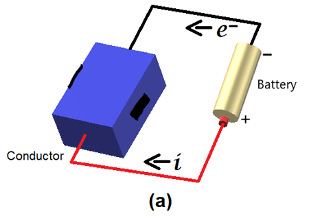
Hall Effect is related with moving charge in a magnetic field. To understand in a practical way, connect a battery to a conductor like shown in image (a) below. The current (i) will start flowing through the conductor from positive to negative of the battery.
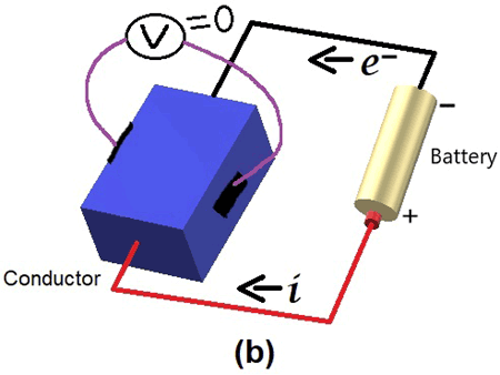
The flow of electrons (e-) will be in opposite direction of current i.e. from negative terminal of battery through conductor to positive terminal of battery. At this moment when we measure the voltage between the conductor as shown in below Image (b) below, then voltage will be zero i.e. potential difference will be zero.
Now bring magnet and create magnetic field between the conductor like Image (c) below.
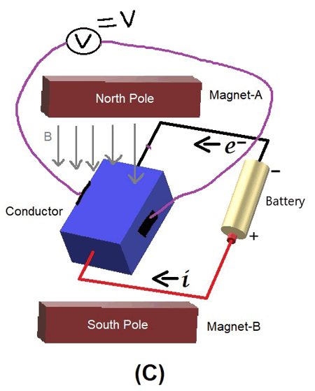
At this condition when voltage is measured across the conductor then there will be some voltage developed. This developed voltage is known as “Hall Voltage” and this phenomenon is known as “Hall Effect”.
Hall Effect Sensor

Hall Effect sensor is a small-scale microelectromechanical systems (MEMS) device for detecting and measuring magnetic fields. These sensors can detect changes in a magnetic field like flux, strength, and direction. When the magnetic flux density around the sensor changes due to the magnet, the sensor detects it and generates an output voltage, and due to this output voltage LED connected to the Magnet sensor changes its state from low to high. In this project, we are using the Hall Effect sensors to detect the North Pole and the South Pole of a magnet.
We have previously Interfaced Hall sensor with Arduino and Raspberry pi and made few projects using Hall sensor like Digital Speedometer, Magnetic Door Alarm, etc.
Circuit Diagram
The circuit diagram for the Magnetic polarity detector is given below. Here two Hall effect sensors are used to detect the North Pole and the South Pole of the magnet. Two LEDs are used to indicate the North and South Pole. Positive pins of magnetic sensors are connected to the OUT pin of 7805 voltage regulator, and Negative pins of Magnetic sensors are connected to GND of 7805 regulators. LEDs are connected to the OUT pin of the magnetic sensor. Two pull-up resistors are connected between OUT pins and positive pins of Magnetic sensors.

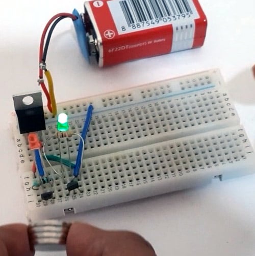
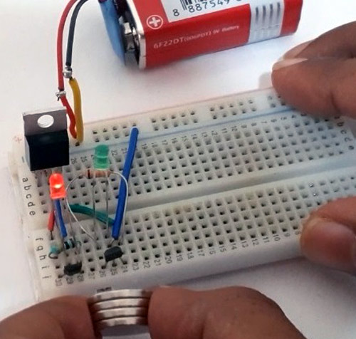
The hardware for the magnet polarity detection circuit looked like this:

Testing the Magnetic Polarity Detector
After connecting the circuit, as shown in the above image, power the setup using a 9V battery. Initially, LEDs will be in High state. Now bring a magnet closer to the Magnet sensors, if you bring south pole near to Red LED, it will turn off as shown in the below figure
And if you bring North pole near to Green LED indicates it becomes off:
This is how you can make your own Magnetic Polarity detector.
A complete working video is given below.
Comments
Has anyone designed a hall
Has anyone designed a hall effect sensor circut to determine direction of rotation of a shaft using two or three sensors?

very good site and will be glad of it