
One of the main applications for Schmitt triggers is interfacing signals between Analog electronics and Digital electronics, and translating levels within different logic families.
One major problem encountered during this process is the pickup of noise. Digital signals are inherently fast because they deal with high frequencies and fast-rising and falling edges. The other side (analog), however, deals with signals that change at a much slower pace in terms of rise and fall times.
To tackle these problems, we will be designing a simple Schmitt trigger using Op-Amp. So, in this article, we will discuss where Schmitt triggers are used, how they work, and how to build a Schmitt trigger using an op-amp.
Why Schmitt Trigger and not just an Op-Amp Comparator?
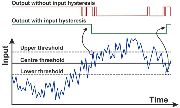
If a simple comparator was used to detect when an analog signal crosses a threshold, due to the slow rise and fall times, there might be multiple transitions through the threshold voltage, which causes multiple pulses on the output, which is undesirable. This behavior is similar to switch bounce and is illustrated in the figure given below.
How Does a Schmitt Trigger Work?
A Schmitt trigger is a device that acts as a comparator. The term trigger in the name comes from the fact that it acts like a latch that triggers when a certain threshold is reached.
In this context, it is a device that changes the high and low thresholds as soon as the input crosses a certain voltage.
This way, multiple transitions are prevented since the threshold voltage changes after the first transition. This prevents unwanted pulses on the output due to noise picked up from the input.
To understand this, it is helpful to take a look at a graph called a hysteresis plot, as shown in the figure given below.
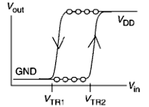
It shows the relationship between the input and how the thresholds change depending on the input.
Following the arrow, the input starts from the ground and keeps increasing until it crosses VTR2. At this point, the output changes state and goes high.
But even if the input crosses VTR2 again, the output will not change state since the threshold has now changed. The input must now go below VTR1 to make the output go low.
By changing the threshold voltage in this fashion, multiple output transitions are prevented while digitizing slow and noisy signals.
How to use Op-Amp as Schmitt Trigger
An op-amp can be used as a comparator, but without the changing thresholds, it falls victim to noise and unwanted output transitions.
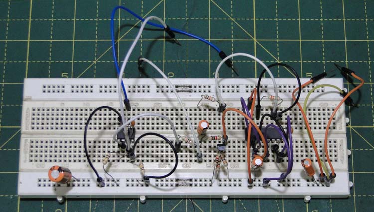
It is easy to implement hysteresis in an op-amp using a few discrete parts that can change the threshold level. In this example, we have built the Schmitt trigger using IC 741 op-amp. The 741 was selected for the purpose of demonstration. The op-amp is powered using a 12V rail.

The inverting input of the op-amp serves as the signal input, and the feedback network is built around the non-inverting input and the output. I built the circuit on a breadboard and my Schmitt trigger using op-amp experiment is shown below. Now, don’t be confused with all the extra components on the board. The 741 op-amp and its connections are shown on the left side. On the right side, we have the sawtooth generator circuit which we are using to test our set-up. If you have a waveform generator you can skip this step.
The threshold voltage is set by the two resistors connected between supply and ground. Since the supply voltage here is 12V, the threshold voltage is 6V.
Another resistor is connected between the output and the non-inverting input, and this is used to change the threshold voltage.
The center threshold voltage is set by the values of the resistor on the voltage divider and is given by the formula:
VCTH = VIN • (RB/(RT + RB))
Where VCTH is the center threshold voltage, VIN is the input voltage, RB is the bottom resistor and RT is the top resistor.
Let’s assume that the output of the op-amp is first low. This means that the resistor connected between the non-inverting input and the output is connected in parallel to the bottom resistor on the voltage divider. Therefore, the lower threshold voltage is given by the formula:
VBTH ≈ VIN • (RB/(RT•RH/(RT + RH)))
Where VBTH is the bottom voltage threshold, VIN is the input voltage, RB is the bottom resistor, RT is the top resistor and RH is the hysteresis resistor.
When the output of the opamp goes high, the feedback resistor is now connected in parallel with the top resistor of the voltage divider, and the threshold voltage is now given by:
VTTH ≈ VIN • (RB/(RB•RH/(RB + RH)))
Where VTTH is the top voltage threshold, RB is the bottom resistor and RH is the hysteresis resistor. The results of applying hysteresis are quite dramatic.
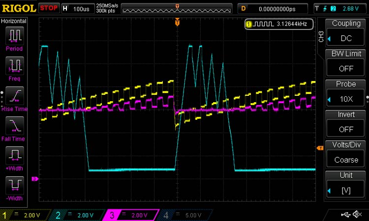
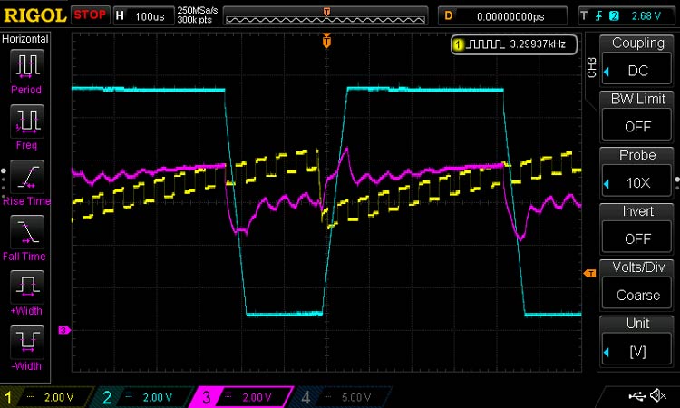
The above image shows the waveforms without hysteresis – yellow waveform is the input – a sawtooth waveform with a superimposed square wave to simulate noise, the pink waveform is the threshold voltage, and the blue waveform is the output waveform. The output waveform has unwanted spikes on the falling edges caused by multiple transitions of the input through the threshold voltage.
A few points to note:
1. A small capacitor has to be added in parallel to the hysteresis resistor to ensure stability and fast response.
2. Limitations in the output swing can show up as errors in the hysteresis threshold, since the hysteresis resistor is not connected directly to supply or ground, instead to a few diode drops above and below the same, because of the op-amp’s output stage.
The above image shows how configuring the op-amp as a Schmitt trigger solves this problem. The output waveform is now clean and has no noise or unwanted transitions. It is also clearly seen that the threshold voltage changes between every high and low transition. You can also check out the complete working demonstration in the video linked below.
Cautions against using Op-Amps as comparators:
1. Op-Amps are designed as amplifiers and their output stages are therefore not suited to fast swings. After saturating at one of the rails, the output might take some time to recover, and this leads to a speed penalty.
2. Op-Amp outputs are slew-rate limited, which might violate edge timing requirements for certain digital systems.
3. Op-Amp inputs usually have a common-mode input limitation, and if exceeded this can lead to problems such as output phase reversal.
Using a Schmitt trigger as a comparator prevents unwanted output transitions and removes noise while digitizing an input signal. Did this tutorial help you to understand the working of Schmitt trigger using op-amp? Do let us know. Also, if you have any questions related to the project, leave them in the comment section below or use our electronics forum.
Postscript:
We would like to mention our thanks and gratitude to Prof. Sam Ben-Yaakov for his time and effort in providing an intuitive explanation on Schmitt-trigger and pointing out the mistakes that were previously present in this article. The article has been reviewed and edited by the author hence forth.

Looking at the formulas for lower and higher thresholds and based on the fact that all resistors have the same it seems that the thresholds are the same?