

We have created a series of Raspberry Pi Tutorials, in which we have covered Interfacing of Raspberry Pi with all the basic components like LED, LCD, button, DC motor, Servo Motor, Stepper Motor, ADC, shift Register, etc. We have also published some simple Raspberry Pi projects for beginners, along with some good IoT projects. Today, in continuation of these tutorials, we are going to Control 8x8 LED Matrix Module by Raspberry Pi. We will write a python program to show characters on the matrix module.
Also check Interfacing 8x8 LED Matrix with Arduino and LED Matrix with AVR Microcontorller.
Components Required:
Here we are using Raspberry Pi 2 Model B with Raspbian Jessie OS. All the basic Hardware and Software requirements are previously discussed, you can look it up in the Raspberry Pi Introduction and Raspberry PI LED Blinking for getting started, other than that we need:
- Raspberry Pi Board
- Power supply (5v)
- 1000uF capacitor (connected across power supply)
- 1KΩ resistor (8 pieces)
8x8 LED Matrix Module:
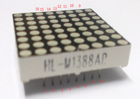
An 8*8 LED matrix module contains 64 LED (Light Emitting Diodes) which are arranged in the form of a matrix, hence the name is LED matrix. These compact modules are available in different sizes and many colors. One can choose them on convenience. The PIN configuration of the module is as shown in picture. Keep in mind that, the pinouts of module are not in order so the PINs should be numbered exactly as shown in picture for avoiding errors.
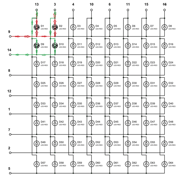
There are 8+8=16 common terminals in the LED Matrix module. Over them, we have 8 common positive terminals and 8 common negative terminals, in the form of 8 rows and 8 columns, for connecting 64 LED in matrix form. If the module were to be drawn in the form of circuit diagram we will have a picture as shown below:
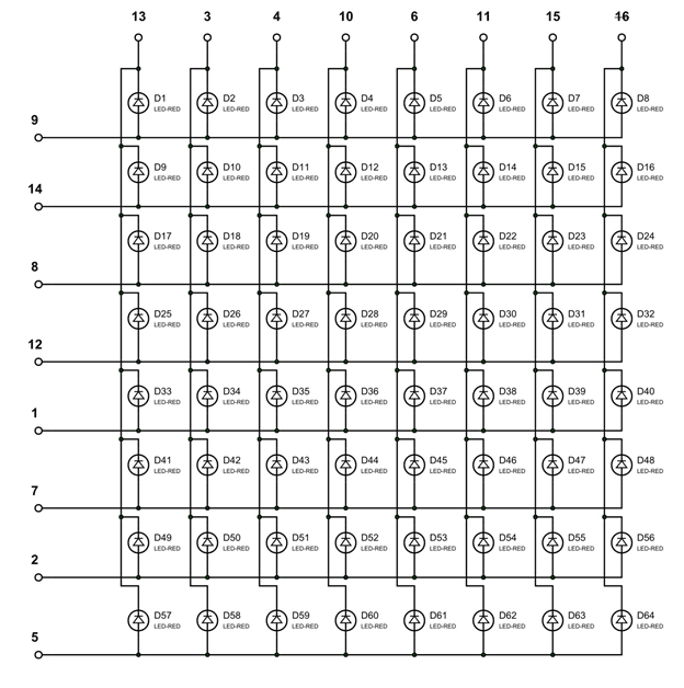
So for 8 rows, we have 8 Common Positive Terminals (9, 14, 8, 12, 17, 2, 5). Consider the first row, the LEDs from D1 to D8 have a common positive terminal and the pin is brought out at PIN9 of LED Matrix module. When we want one or all LEDs in a ROW to be ON, The corresponding pin of LED MODULE should be powered with +3.3v.
Similar to common positive terminals, we have 8 Common Negative Terminals as columns (13, 3, 4, 10, 6, 11, 15, 16). For grounding any LED in any column the respective common negative terminal to be grounded.
Circuit Explanation:
The connections which are done between Raspberry Pi and LED matrix module are shown in below table.
|
LED Matrix Module Pin no. |
Function |
Raspberry Pi GPIO Pin No. |
|
13 |
POSITIVE0 |
GPIO12 |
|
3 |
POSITIVE1 |
GPIO22 |
|
4 |
POSITIVE2 |
GPIO27 |
|
10 |
POSITIVE3 |
GPIO25 |
|
6 |
POSITIVE4 |
GPIO17 |
|
11 |
POSITIVE5 |
GPIO24 |
|
15 |
POSITIVE6 |
GPIO23 |
|
16 |
POSITIVE7 |
GPIO18 |
|
9 |
NEGATIVE0 |
GPIO21 |
|
14 |
NEGATIVE1 |
GPIO20 |
|
8 |
NEGATIVE2 |
GPIO26 |
|
12 |
NEGATIVE3 |
GPIO16 |
|
1 |
NEGATIVE4 |
GPIO19 |
|
7 |
NEGATIVE5 |
GPIO13 |
|
2 |
NEGATIVE6 |
GPIO6 |
|
5 |
NEGATIVE7 |
GPIO5 |
Here is the Final circuit diagram for Interfacing 8x8 LED Matrix with Raspberry Pi:

Working Explanation:
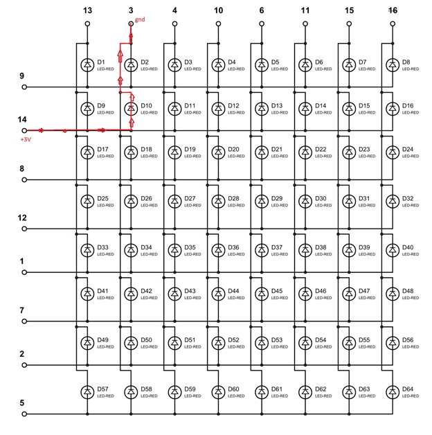
Here we will use Multiplexing Technique to show characters on the 8x8 LED Matrix Module. So let’s discuss about this multiplexing in detail. Say if we want to turn on LED D10 in the matrix, we need to power the PIN14 of module and ground the PIN3 of module. With this LED D10 will turn ON as shown in below figure. This should also be checked first for MATRIX to know everything is in order.
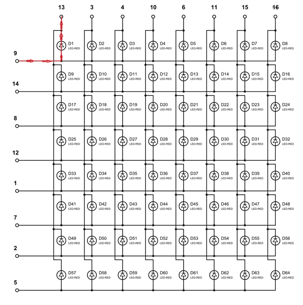
Now, say if we want to turn on D1, we need to power PIN9 of matrix and ground the PIN13. With that LED D1 will glow. The current direction in this case is shown in below figure.
Now for the tricky part, consider we want to turn on both D1 and D10 at the same time. So we should power both PIN9, PIN14 and ground both PIN13, PIN3. This will turn on the LED D1 and D10, but along with that it will also turn on LED D2 and D9. It’s because they share common terminals. So if we want to turn on the LEDs along the diagonal, we will be forced to turn ON all the LEDs along the way. This is shown in below figure:
To avoid this problem, we use a technique called Multiplexing. We have also discussed this Multiplexing Technique while interfacing 8x8 LED Matrix with AVR, here we are explaining again. This same multiplexing technique is also used in Scrolling Text on 8x8 LED matrix with Arduino and with AVR microcontroller.
The human eye cannot capture a frequency more than 30 HZ. That is if a LED goes ON and OFF continuously at the rate of 30HZ or more. The eye sees the LED as continuously ON. However this is not the case and LED will be actually turning ON and OFF constantly. This technique is called Multiplexing.
Let’s say for example, we want to only turn on LED D1 and LED D10 without turning on D2 and D9. Trick is, we will first provide power to only LED D1 using PIN 9 & 13 and wait for 1mSEC, and then we will turn it OFF. Then we will provide power to LED D10 using PIN 14 & 3 and wait for 1mSEC then will turn it OFF. The cycle goes continuously with high frequency and D1 & D10 will getting On and Off rapidly and both the LEDs will appear to be continuously ON to our eye. Means we are only providing power to the one row (LED) at a time, eliminating the chances of turning on other LEDs in other rows. We will use this technique to show all characters.
We can further understand it by one example, like if we want to display “A” on the matrix, like shown below:
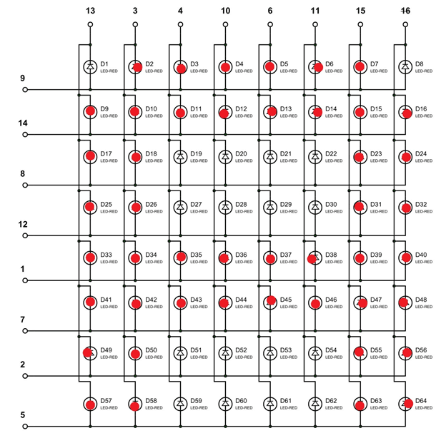
As told we will turn ON one row in an instant,
At t=0m SEC, PIN09 is set HIGH (other ROW pins are LOW at this time) at this time,PIN3,PIN4,PIN10,PIN6,PIN11,PIN15 are grounded(other COLUMN pins are HIGH at this time)
At t=1m SEC, PIN14 is set HIGH (other ROW pins are LOW at this time )at this time, PIN13,PIN3,PIN4,PIN10,PIN6,PIN11,PIN15,PIN16 are grounded(other COLUMN pins are HIGH at this time)
At t=2m SEC, PIN08 is set HIGH (other ROW pins are LOW at this time )at this time, PIN13,PIN3,PIN15,PIN16 are grounded(other COLUMN pins are HIGH at this time)
At t=3m SEC, PIN12 is set HIGH (other ROW pins are LOW at this time )at this time, PIN13,PIN3,PIN15,PIN16 are grounded(other COLUMN pins are HIGH at this time)
At t=4m SEC, PIN01 is set HIGH (other ROW pins are LOW at this time )at this time, PIN13,PIN3,PIN4,PIN10,PIN6,PIN11,PIN15,PIN16 are grounded(other COLUMN pins are HIGH at this time)
At t=5m SEC, PIN07 is set HIGH (other ROW pins are LOW at this time )at this time, PIN13,PIN3,PIN4,PIN10,PIN6,PIN11,PIN15,PIN16 are grounded(other COLUMN pins are HIGH at this time)
At t=6m SEC, PIN02 is set HIGH (other ROW pins are LOW at this time )at this time, PIN13,PIN3,PIN15,PIN16 are grounded(other COLUMN pins are HIGH at this time)
At t=7m SEC, PIN05 is set HIGH (other ROW pins are LOW at this time )at this time, PIN13,PIN3,PIN15,PIN16 are grounded(other COLUMN pins are HIGH at this time)
At this speed, the display will be seen as continuously showing “A” character as shown in figure.
The Python Program for showing Characters on LED Matrix using Raspberry Pi is given below. Program is well explained by comments. Port Values for each character are given in the program. You can show whatever characters you want by just changing the ‘pinp’ values in the ‘for loops’ in the given program. Also check the Demo Video below.
Complete Project Code
#working

import RPi.GPIO as IO  #calling for header file which helps in using GPIO’s of PI

import time            #calling for time to provide delays in program

IO.setwarnings(False)  #do not show any warnings

x=1

y=1

IO.setmode (IO.BCM)  #programming the GPIO by BCM pin numbers. (like PIN29 as'GPIO5')

IO.setup(12,IO.OUT)  #initialize GPIO12 as an output.

IO.setup(22,IO.OUT)  #initialize GPIO22 as an output.

IO.setup(27,IO.OUT)

IO.setup(25,IO.OUT)

IO.setup(17,IO.OUT)

IO.setup(24,IO.OUT)

IO.setup(23,IO.OUT)

IO.setup(18,IO.OUT)

IO.setup(21,IO.OUT)

IO.setup(20,IO.OUT)

IO.setup(26,IO.OUT)

IO.setup(16,IO.OUT)

IO.setup(19,IO.OUT)

IO.setup(13,IO.OUT)

IO.setup(6,IO.OUT)

IO.setup(5,IO.OUT)
PORTVALUE = [128,64,32,16,8,4,2,1]

#value of pin in each port

A=[0,0b01111111,0b11111111,0b11001100,0b11001100,0b11001100,0b11111111,0b01111111]

B =[0,0b00111100,0b01111110,0b11011011,0b11011011,0b11011011,0b11111111,0b11111111]

C= [0,0b11000011,0b11000011,0b11000011,0b11000011,0b11100111,0b01111110,0b00111100]

D=[0,0b01111110,0b10111101,0b11000011,0b11000011,0b11000011,0b11111111,0b11111111]

E=[0,0b11011011,0b11011011,0b11011011,0b11011011,0b11011011,0b11111111,0b11111111]

F=[0,0b11011000,0b11011000,0b11011000,0b11011000,0b11011000,0b11111111,0b11111111]

G=[0b00011111,0b11011111,0b11011000,0b11011011,0b11011011,0b11011011,0b11111111,0b11111111]

H=[0,0b11111111,0b11111111,0b00011000,0b00011000,0b00011000,0b11111111,0b11111111]

I=[0b11000011,0b11000011,0b11000011,0b11111111,0b11111111,0b11000011,0b11000011,0b11000011]

J=[0b11000000,0b11000000,0b11000000,0b11111111,0b11111111,0b11000011,0b11001111,0b11001111]

K=[0,0b11000011,0b11100111,0b01111110,0b00111100,0b00011000,0b11111111,0b11111111]

L=[0b00000011,0b00000011,0b00000011,0b00000011,0b00000011,0b00000011,0b11111111,0b11111111]

M=[0b11111111,0b11111111,0b01100000,0b01110000,0b01110000,0b01100000,0b11111111,0b11111111]

N=[0b11111111,0b11111111,0b00011100,0b00111000,0b01110000,0b11100000,0b11111111,0b11111111]

O=[0b01111110,0b11111111,0b11000011,0b11000011,0b11000011,0b11000011,0b11111111,0b01111110]

P=[0,0b01110000,0b11111000,0b11001100,0b11001100,0b11001100,0b11111111,0b11111111]

Q=[0b01111110,0b11111111,0b11001111,0b11011111,0b11011011,0b11000011,0b11111111,0b01111110]

R=[0b01111001,0b11111011,0b11011111,0b11011110,0b11011100,0b11011000,0b11111111,0b11111111]

S=[0b11001110,0b11011111,0b11011011,0b11011011,0b11011011,0b11011011,0b11111011,0b01110011]

T=[0b11000000,0b11000000,0b11000000,0b11111111,0b11111111,0b11000000,0b11000000,0b11000000]

U=[0b11111110,0b11111111,0b00000011,0b00000011,0b00000011,0b00000011,0b11111111,0b11111110]

V=[0b11100000,0b11111100,0b00011110,0b00000011,0b00000011,0b00011110,0b11111100,0b11100000]

W=[0b11111110,0b11111111,0b00000011,0b11111111,0b11111111,0b00000011,0b11111111,0b11111110]

X=[0b01000010,0b11100111,0b01111110,0b00111100,0b00111100,0b01111110,0b11100111,0b01000010]

Y=[0b01000000,0b11100000,0b01110000,0b00111111,0b00111111,0b01110000,0b11100000,0b01000000]

Z=[0b11000011,0b11100011,0b11110011,0b11111011,0b11011111,0b11001111,0b11000111,0b11000011]
def PORT(pin):  #assigning GPIO state by taking 'pin' value

    if(pin&0x01 == 0x01):

        IO.output(21,0)   #if bit0 of 8bit 'pin' is true pull PIN21 low

    else:

        IO.output(21,1)   #if bit0 of 8bit 'pin' is false pull PIN21 high

    if(pin&0x02 == 0x02):

        IO.output(20,0)   #if bit1 of 8bit 'pin' is true pull PIN20 low

    else:

        IO.output(20,1)   #if bit1 of 8bit 'pin' is false pull PIN20 high

    if(pin&0x04 == 0x04):

        IO.output(26,0)   #if bit2 of 8bit 'pin' is true pull PIN26 low

    else:

        IO.output(26,1)   #if bit2 of 8bit 'pin' is false pull PIN26 high

    if(pin&0x08 == 0x08):

        IO.output(16,0)

    else:

        IO.output(16,1)


if(pin&0x10 == 0x10):

        IO.output(19,0)

    else:

        IO.output(19,1)

    if(pin&0x20 == 0x20):

        IO.output(13,0)

    else:

        IO.output(13,1)

    if(pin&0x40 == 0x40):

        IO.output(6,0)

    else:

        IO.output(6,1)

    if(pin&0x80 == 0x80):

        IO.output(5,0)

    else:

        IO.output(5,1)
def PORTP(pinp):    #assigning GPIO logic for positive terminals by taking 'pinp' value

    if(pinp&0x01 == 0x01):

        IO.output(12,1)     #if bit0 of 8bit 'pinp' is true pull PIN12 high

    else:

        IO.output(12,0)     #if bit0 of 8bit 'pinp' is false pull PIN12 low

    if(pinp&0x02 == 0x02):

        IO.output(22,1)     #if bit1 of 8bit 'pinp' is true pull PIN22 high

    else:

        IO.output(22,0)     #if bit1 of 8bit 'pinp' is false pull PIN22 low

    if(pinp&0x04 == 0x04):

        IO.output(27,1)     #if bit2 of 8bit 'pinp' is true pull PIN27 high

    else:

        IO.output(27,0)     #if bit2 of 8bit 'pinp' is false pull PIN27 low

    if(pinp&0x08 == 0x08):

        IO.output(25,1)

    else:

        IO.output(25,0)

    if(pinp&0x10 == 0x10):

        IO.output(17,1)

    else:

        IO.output(17,0)

    if(pinp&0x20 == 0x20):

        IO.output(24,1)

    else:

        IO.output(24,0)

    if(pinp&0x40 == 0x40):

        IO.output(23,1)

    else:

        IO.output(23,0)

    if(pinp&0x80 == 0x80):

        IO.output(18,1) #if bit7 of 8bit 'pinp' is true pull PIN18 high

    else:

        IO.output(18,0) #if bit7 of 8bit 'pinp' is false pull PIN18 low
while 1:

    for y in range (100):   #execute loop 100 times

        for x in range (8): #execute the loop 8 times incrementing x value from zero to seven

            pin  = PORTVALUE[x]  #assigning value to 'pin' for each digit

            PORT(pin);  #mapping appropriate GPIO

            pinp= C[x]  #assigning character 'C' value to 'pinp'

            PORTP(pinp); #turning the GPIO to show character 'C'

            time.sleep(0.0005) #wait for 0.5msec
    for y in range (100):

        for x in range (8):

            pin  = PORTVALUE[x]

            PORT(pin);

            pinp= I[x]

            PORTP(pinp);

            time.sleep(0.0005)


for y in range (100):

        for x in range (8):

            pin  = PORTVALUE[x]

            PORT(pin);

            pinp= R[x]

            PORTP(pinp);

            time.sleep(0.0005)
    for y in range (100):

        for x in range (8):

            pin  = PORTVALUE[x]

            PORT(pin);

            pinp= C[x]

            PORTP(pinp);

            time.sleep(0.0005)
    for y in range (100):

        for x in range (8):

            pin  = PORTVALUE[x]

            PORT(pin);

            pinp= U[x]

            PORTP(pinp);

            time.sleep(0.0005)
    for y in range (100):

        for x in range (8):

            pin  = PORTVALUE[x]

            PORT(pin);

            pinp= I[x]

            PORTP(pinp);

            time.sleep(0.0005)
    for y in range (100):

        for x in range (8):

            pin  = PORTVALUE[x]

            PORT(pin);

            pinp= T[x]

            PORTP(pinp);

            time.sleep(0.0005)
    for y in range (100):

        for x in range (8):

            pin  = PORTVALUE[x]

            PORT(pin);

            pinp= D[x]

            PORTP(pinp);

            time.sleep(0.0005)


    for y in range (100):

        for x in range (8):

            pin  = PORTVALUE[x]

            PORT(pin);

            pinp= I[x]

            PORTP(pinp);

            time.sleep(0.0005)
    for y in range (100):

        for x in range (8):

            pin  = PORTVALUE[x]

            PORT(pin);

            pinp= G[x]

            PORTP(pinp);

            time.sleep(0.0005)


    for y in range (100):

        for x in range (8):

            pin  = PORTVALUE[x]

            PORT(pin);

            pinp= E[x]

            PORTP(pinp);

            time.sleep(0.0005)


    for y in range (100):

        for x in range (8):

            pin  = PORTVALUE[x]

            PORT(pin);

            pinp= S[x]

            PORTP(pinp);

            time.sleep(0.0005)


    for y in range (100):

        for x in range (8):

            pin  = PORTVALUE[x]

            PORT(pin);

            pinp= T[x]

            PORTP(pinp);

            time.sleep(0.0005)
    pinp= 0

    PORTP(pinp);

    time.sleep(1)
Comments
You should add how to run the
You should add how to run the script. I get NameError: name 'pin' is not defined
Line 71 roughly
17 is typo (separate two
17 is typo (separate two numbers with comma):
"8 Common Positive Terminals (9, 14, 8, 12, 17, 2, 5)"

I see the resistors in the diagram but i cannot see the capacitor.
and also why using 1 K resistors if to light a led with the pi you just need a 330 resistor