

Road accidents became a matter of concern due to the huge increase in traffic. The primary cause of accidents is due to the drowsiness of drivers in the nighttime. Fatigue and drowsiness are some of the leading causes of major accidents on Highways. The only solution to this problem is detecting the drowsiness and alerting the driver.
So, in this project, we have thought of building a Driver Drowsiness Detection and Alerting System for Drivers using Arduino Nano, Eye blink Sensor, and RF Transceiver module. The basic purpose of this system is to track the driver’s eye movements using Eye blink Sensor and if the driver is feeling drowsy, then the system will trigger a warning message using a loud buzzer alert. Previously we have also built a Driver Drowsiness detector using Raspberry Pi & OpenCV.
Materials Required for Building a Drowsiness Detector
- Arduino Nano
- Eyeblink Sensor
- RF Transceiver Module
- HD12E & HD12D IC
- Buzzer
- 9V Battery
- 12V DC power supply
Eye Blink Sensor

The eye blink sensor is used to detect the eye blinks and using which we can also detect the activities like the Drowsiness of the driver while driving. It works based on the technology of Infrared LED. It contains an Infrared transmitter and Receiver LED which is used to detect the eye blink. The working of the simple IR sensor is shown as below:
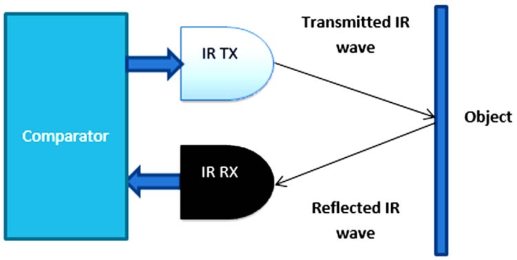
As shown in the image above, infrared sensors consist of two elements: infrared transmitter which acts as the source, and infrared receiver which acts as the receiver. Infrared sources include an IR LED and Infrared detectors include photodiodes. The energy emitted by the infrared source is reflected by an object and falls back on the infrared detector. When the light emitted by the IR LED falls on the receiver, the resistance of the photodiode falls down significantly. This photoreceiver is connected with a potentiometer to form a voltage divider circuit, which gives a variable analog output when blinking activity is detected.
When the incident radiation is more on the photodiode, the voltage drop across the series resistor/Potentiometer will be high. In the Comparator IC which is nothing but an Operational Amplifiers, or Op-amps, both the reference analog voltage and the actual output voltages are compared. If the voltage across the resistor series to photodiode is greater than that of the reference voltage, the output of the comparator is high, else Low. As the output of the comparator is connected to an LED, it glows when the sensor detects some activity such as eye blinking. The threshold voltage can be adjusted by adjusting the potentiometer depending on the environmental conditions.
Technical Specifications of Eye Blink Sensor
- Working Voltage: 5V DC
- Output: TTL(5V/0V)
- Onboard 3 Pin Header for connections
- Infrared Technology
433 MHz RF Transceiver Module
The RF stands for Radio Frequency. The corresponding frequency range varies between 30 kHz & 300 GHz. Here we are using a 433 MHz RF Transceiver Module. This RF module comprises a 433 MHz RF Transmitter and RF Receiver. The transmitter/receiver (Tx/Rx) pair operates at a frequency of 433 MHz. An RF transmitter receives serial data and transmits it wirelessly through RF through its antenna. The transmitted data is received by an RF receiver operating at the same frequency as that of the transmitter.
RF Transmitter
The RF transmitter module uses Amplitude Shift Keying (ASK) and operates at 433MHz. The transmitter module takes serial data input and transmits that signal through RF. The transmitted signals are then received by the receiver module wirelessly.
- Ground: Transmitter ground. Connect to the ground plane
- Data: Serial data input pin
- VCC: Supply voltage; 5V
- ANT: Antenna output pin
RF Receiver
The RF receiver module receives the data and sends it to the data OUTPUT pin. The output data can be decoded by the Microcontroller for further action.
- Ground: Receiver ground. Connect to the ground plane
- Data: Serial data output pin
- VCC: Supply voltage; 5V
- ANT: Antenna output pin
Driver Drowsiness Detector Circuit Diagram
Driver Drowsiness Detector consists of RF Transmitter and Receiver section. The transmitter section consists of an RF Transmitter and Eye Blink Sensor and the receiver side uses Arduino Uno with RF receiver for data processing. We previously used the same 433 MHz RF modules with Arduino for building projects like Arduino RC Boat, hand gesture controlled robot, etc. The circuit diagram for the transmitter and receiver section is given below.
Transmitter Side

As shown in the figure, first the 9V DC battery is stepped down to 5V DC using a 7805 voltage regulator, and then the 5V DC supply is given to the Eye Blink Sensor and RF Transmitter. The output pin of the eye blink sensor is fed to the RF transmitter to transmit it wirelessly to the receiver end.
Receiver Side
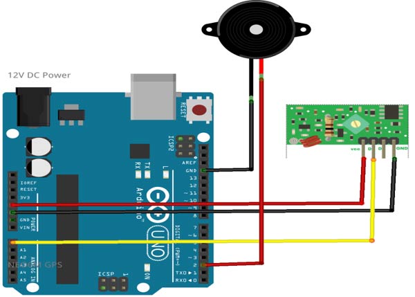
As shown in the figure, on the receiver side the RF receiver is connected to a 5V DC power supply from Arduino. The Arduino is powered from a 12V DC power supply externally. The output of the RF receiver is fed to the Arduino Analog pin. The Buzzer is connected to the Digital pin of Arduino as shown.
Programming Arduino Nano for Drowsiness Detection
After a successful hardware connection for both the transmitter side and receiver side, now it’s time to upload the code to Arduino Nano that is connected to the receiver side. This complete code is given at the end of the document. First, let’s understand the code stepwise below:
First, required variables need to be declared as shown below.
int flag=0;
int t1=0;
int t2=0;
In Setup(), all the initializations are made including Serial port initializations and pin declarations as shown below.
void setup() {
  Serial.begin(9600);
  pinMode(2,OUTPUT);
}
The serial data output of the RF receiver is read from the analog pin A0 and stored in a variable as shown. To check the reference values, we can see it using a serial monitor.
  int x=analogRead(A0);
  Serial.println(x);
After determining the reference value, an if-else statement is written to detect the drowsiness. As shown in the code below, millis() function is used to know the duration for which the eye blink occurred. If it is greater than that value then it beeps a buzzer to alert the driver. In our case, the time duration is given as 1000 ms or 1 Sec.
if(x<400 && flag==0) {
    flag=1;
    t1=millis();
}
else if(x>400 && flag==1) {
    flag=0;
    t2=millis();
    Serial.println(t2-t1);
    if((t2-t1)>1000) {
        digitalWrite(2,HIGH);
        Serial.println("Alert!!!!!!!!!!!!!!!!!");
        delay(2000);
        digitalWrite(2,LOW);
    }
    else;
  }
}
Drowsiness Detector Testing
After successful uploading of the program to Arduino, now it’s time to test the working. First switch on the power in both Transmitter and Receiver sides. Ensure power is coming at both ends. Wear the Sunglass having eye blink sensor and try blinking eye normally, there should be a LED glowing on the sensor. If not, then try to vary the potentiometer to change the sensitivity till it detects the eye blink successfully. After successful detection, try for drowsiness by delayed blinking, it should alert by beeping the buzzer.

So that’s all about building a Sleep Sensing and Alerting System for Drivers using Arduino Nano and Eye Blink Sensor. Complete code and Working video are given below. If you have any doubts, you can post them in the comment section or in our forum.
Complete Project Code
Eye_Blink_Arduino.ino
int flag=0;
int t1=0;
int t2=0;
void setup()
{
  Serial.begin(9600);
  pinMode(2,OUTPUT);

}
void loop()
{
  int x=analogRead(A0);
  //Serial.println(x);

    if(x<400 && flag==0)
  {
    flag=1;
    t1=millis();
  }
  else if(x>400 && flag==1)
  {
    flag=0;
    t2=millis();
    Serial.println(t2-t1);
    if((t2-t1)>1000)
    {
      digitalWrite(2,HIGH);
      Serial.println("Alert2!!!!!!!!!!!!!!!!!");
      delay(2000);
      digitalWrite(2,LOW);
    }
    else;
  }
}Comments
Dear Mr. Parida-
That is a fantastic concept, and very beneficial to the world!
May I throw my two cents in?
Get rid of glasses, and make sensors that can be placed around the eye orbit, or use a small camera that can be adjusted to the drivers dimensions in its field of view.
People would be more apt to use it if there is nothing placed on the face.
Good luck on this and other adventures.
R.Mahinske

你好,你做的項目很棒,對全世界開車人,有做貢獻,你可以申請專利也可以在升級功能,越小越好,如用Attiny13或85,如果你打算要升請專利而量產時,最好不要發佈這平台的,畢竟是你私人專利。// Hello, the project you have done is great, and you can contribute to the drivers around the world. You can apply for a patent or upgrade the function. The smaller the better, such as Attiny13 or 85. If you plan to increase the amount of patents During production, it is best not to publish this platform, after all, it is your private patent