
Motion sensor circuits are there on the Internet for quite a while now. These circuits are mainly used to drive AC load (like lights, fans) in home automation or IoT projects. It is also very common in manufacturing industries, like on conveyor belts where the presence/position of a particular object has to be detected.
So, in this tutorial, we are going to use an IR sensor with a NE555 Timer IC to detect motion and switch the AC load according to that. The 555 timer IC is used as a switch here. Since this circuit uses a digital timer IC, so the operation of the circuit is fast and accurate with even faster detection speeds. In our previous tutorial, we learned about the 555-timer as a latching circuit. This is the application of that circuit, we will also demonstrate the circuit by designing it on a piece of perf-board.
Components Required to Build a Motion Detector Circuit
A list of components required to build a motion detector circuit is given below:
- 555 timer IC
- 220KΩ resistors*2
- 100kΩ resistor
- 1KΩ resistor
- 1uf electrolytic capacitor
- LED
- 220Ω resistor
- SPDT Relay*2
- In4007 diode*2
- BC547 NPN transistor
- BC557 pnp transistor
- DC jack
- IR sensor module
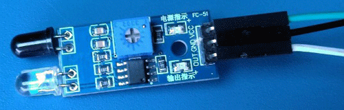
IR Sensor Module – A Brief Introduction
IR stands for infrared radiations/light and it is the most common way of detecting motion. There are 2 types of IR sensors:
Infrared comes in the place of the electromagnetic spectrum which is not visible to naked eyes. All the hot objects generate these IR radiations and by detecting these radiations, we can sense the motion. The PIR sensor does not emit any IR radiation but only detects the radiations and thus it is called “passive”. On the other hand, we have IR modules that send an IR pulse continuously and when it bounces back from an object, the module can detect it by using a photodiode. This photodiode in this case can only detect Infrared light and not visible light.
Two main components of an IR sensor module are IR LED and photodiode. LED looks exactly like a normal LED but it emits IR instead of the visible colors that we are familiar with. Photodiode is the key component that detects the bounced back radiations.
In this project, we are using an active IR sensor module as it is readily available, affordable, and easy to use.
555 Timer Motion Detector Circuit Diagram
The complete motion detector circuit using a 555 timer is given below.

In the circuit, pins 2 and 6 are connected, and also pins 4 and 8 are connected. The output of the voltage divider circuit is connected to pin 6 of the IC. One resistor of the voltage divider circuit is connected via a 1uF capacitor to the output pin 3 through the 100k resistor. A relay with its driver circuit is connected between pin 2 and the capacitor’s positive terminal. An LED is also connected through its current limiting resistor at the output of the IC. The base of the NPN transistor used for controlling the output relay is connected to the output pin 3 of the IC via a 1K resistor. The base of the PNP transistor driving the switching relay of the IC is connected to the output of the IR sensor module.
Working of Motion Detector Circuit
Working of the motion sensor circuit is given below:
- Initially, due to the voltage divider, half of the supply voltage is there on pins 2 and 6 because we are using a voltage divider with an equal value of resistors and thus the output of the IC is OFF.
- When the motion is detected by the sensor, the capacitor starts to draw current through the resistor R3 to charge, and thus the voltage drop across the resistor changes which in turn makes the voltage at pin 2 go below the 1/3 of supply voltage mark. This turns the output of the IC ON.
- Now the capacitor is fully charged to the supply voltage through the 100kΩ resistor. When the motion is detected, again pin 6 of the timer IC detects the charged capacitor which obviously is at the supply voltage and thus goes more than the 2/3 mark. This turns the output of the IC OFF.
- If you observe the circuit a little close, you can see that we can use a BJT instead of relay and you are correct but unfortunately this will not work. The reason is again the difference between the ideal and the real world. We use BJTs everywhere but they are not perfect switches and have some leakage current which in this case messes up with the circuit. We need an ideal switch in this case and thus we are using a relay.
- The transistors are used to drive the relays. We are using a PNP transistor to drive the main relay because the IR sensor module gives a constant supply voltage at its output and when it detects something, it pulls the voltage to the ground. We can use an NPN transistor to drive the output relay as the IC has active high output.
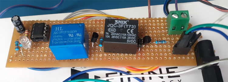
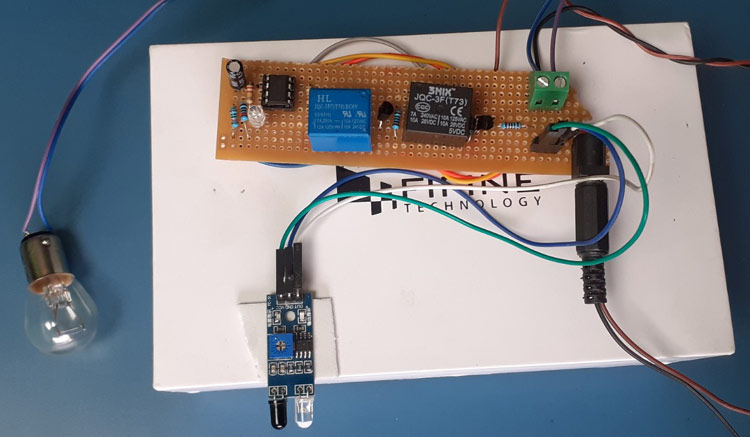
Demonstration of Motion Sensor Circuit
By following the 555 timer motion detector circuit diagram given above, I created the circuit on perf-board, the video of which is available at the end of the article. Also, the pictures related to the circuit are given below.
This is how you can use the famous 555-timer IC in combination with an IR sensor to design a high-speed motion sensor circuit. If you have any doubts related to the circuit, feel free to leave your comment below.
Comments
I came to your site when i…
I came to your site when i was searching for ir detector DIY schema´s. I want to build the circuits. However, in my opinion
there is something with the connection of the 2 relays...
Where is the Powersupply (ground for Q1 and VCC for Q2)? I must admit that i never worked wih relays...
best regards

Hi , I am attempting to build this for one of my classes. Could you by any chance post more pictures of the circuit and how everything is connected since I am still learning how to read the schematics? Thanks.