

Measuring the speed/rpm of a Vehicle or a motor has always been a fascinating project for us to try. So, in this project we are going to build one using the Industrial ready PIC microcontrollers. We will use a piece of magnet and a Hall Sensor to measure the speed. There are other ways/sensors to measure the speed but, using a hall sensor is cheap and also can be used on any type of motor/Vehicle. By doing this project we will also enhance our skills in learning PIC16F877A since the project involves the use of Interrupts and Timers. At, the end of this project you will be able to calculate the speed and distances covered by any rotating object and display them on a 16x2 LCD screen. Lets start with this Digital Speedometer and Odometer Circuit with PIC.
Materials Required:
- PIC16F877A
- 7805 Voltage Regulator
- Hall Effect Sensor (US1881/04E)
- 16*2 LCD display
- A small piece of magnet
- Connecting wires
- Capacitors
- Breadboard.
- Power supply
Calculating Speed and Distance Covered:
Before we actually start building the circuit, let us understand how we will be using a Hall sensor and a magnet to calculate the speed of a wheel. Previously we have used same Technique to build Arduino Speedometer which displays readings on Android Smart Phone.
A Hall sensor is a device which can detect the presence of a magnet based on its polarity. We stick a small piece of magnet on the wheel and place the hall sensor near it in such a way that every time the wheel rotates the hall sensor detects it. We then use the help of timers and Interrupts on our PIC Microcontroller to calculate the time taken for one complete rotation of the wheel.

Once the time taken is known we can calculate the RPM by using the below formulae, Where 1000/time taken will give us the RPS and further multiplying it with 60 will give you the RPM
rpm = (1000/timetaken) * 60;
Where (1000/timetaken) gives the rps (Revolutions per second) and it is multiplied by 60 to convert rps to rpm (Revolutions per minute).
Now to calculate the velocity of the vehicle we have to know the radius of the wheel. In our project we have used a small toy wheel which has a radius of just 3cm. But, we assumed the radius of wheel is to be 30cm (0.3m) so that we can visualize the readings.
The value is also multiplied with 0.37699 since we know that Velocity = (RPM (diameter * Pi) / 60). The formulae is simplified down to
v= radius_of_wheel * rpm * 0.37699;
Once we calculate the velocity we can also calculate the distance covered by using a similar method. With our Hall and magnet arrangement we know that how many times the wheel have rotated. We also know the radius of the wheel, using which we can find the circumference of the wheel, assuming the radius of the wheel to be 0.3m(R) the values of circumference Pi*R*R will be 0.2827. This means that for every time the hall sensor meets the magnet a distance of 0.2827 meters is covered by the wheel.
Distance_covered = distance_covered + circumference_of_the_circle
Since, now we know how this project will work lets proceed to our circuit diagram and start building it.
Circuit Diagram and Hardware Setup:

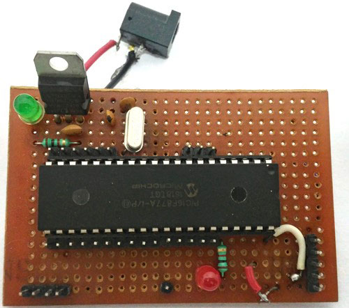
The Circuit Diagram of this Speedometer and Odometer Project is very simple and can be built on a breadboard. If you have been following the PIC tutorials then you can also reuse the hardware that we used for learning PIC microcontrollers. Here we have used the same perf Board which we have built for LED Blinking with PIC Microcontroller, as shown below:
The pin connections for the PIC16F877A MCU are given in the table below.
|
S.No: |
Pin Number |
Pin Name |
Connected to |
|
1 |
21 |
RD2 |
RS of LCD |
|
2 |
22 |
RD3 |
E of LCD |
|
3 |
27 |
RD4 |
D4 of LCD |
|
4 |
28 |
RD5 |
D5 of LCD |
|
5 |
29 |
RD6 |
D6 of LCD |
|
6 |
30 |
RD7 |
D7 of LCD |
|
7 |
33 |
RB0/INT |
3rd pin of Hall sensor |
Once you build your project it should look something like this in the picture below
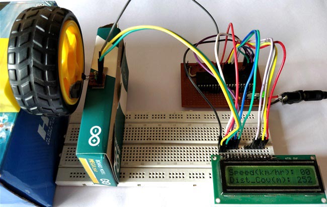
As you can see I have used two boxes to place the Motor and a hall sensor in nearby position. You can fix the magnet on your rotating object and intact the hall sensor close to it in such a way that it can detect the magnet.
Note: Hall sensor have polarities, so make sure which pole it is detecting and place it accordingly.
Also make sure you use a Pull-up resistor with the output pin of the hall sensor.
Simulation:
The Simulation for this project is done using Proteus. Since the project involves moving objects it is not possible to demonstrate the complete project using simulation but the working of the LCD can be verified. Simply load the hex file to the Simulation and simulate it. You will be able to notice the LCD working as shown below.
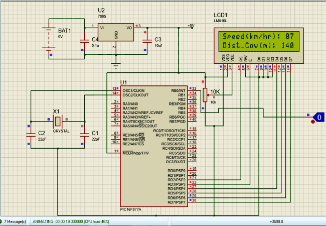
To check of the speedometer and odometer are working I have replaced the Hall sensor with a Logic state device. During the simulation you can click on the logic state button to trigger the Interrupt and check if the speed and distance covered is getting updated as shown above.
Programming your PIC16F877A:
As said earlier we will be using the help of timers and interrupts in the PIC16F877A Microcontroller to calculate the time taken for one complete rotation of the wheel. We have already learnt how to use Timers in our pervious tutorial. I have given the complete code of the project at the end of this article. Further I have explained few important lines below.
The below lines of code initializes the Port D as output pins for LCD interfacing and RB0 as input pin for using it as external Pin. Further we have enabled internal pull-up resistor using the OPTION_REG and have also set 64 as presale. WE then Enable Global and Peripheral Interrupt to enable Timer and External Interrupt. To define RB0 as external interrupt bit INTE should be made high. The Overflow is value is set to be 100 so that for every 1 millisecond the timer interrupt flag TMR0IF will be triggered. This will help to run a millisecond timer to determine the time taken in millisecond:
    TRISD = 0x00; //PORTD declared as output for interfacing LCD
    TRISB0 = 1;        //DEfine the RB0 pin as input to use as interrupt pin
    OPTION_REG = 0b00000101;  // Timer0 64 as prescalar // Also Enables PULL UPs
    TMR0=100;       // Load the time value for 1ms; delayValue can be between 0-256 only
    TMR0IE=1;       //Enable timer interrupt bit in PIE1 register
    GIE=1;          //Enable Global Interrupt
    PEIE=1;         //Enable the Peripheral Interrupt
    INTE = 1;          //Enable RB0 as external Interrupt pin
The below function will get executed each time an Interrupt is detected. We can name the function as per our wish so I have named it as speed_isr(). This program deals with two interrupts one is Timer Interrupt and the other is External Interrupt. Whenever a Timer Interrupt occurs the flag TMR0IF goes high, to clear and reset the interrupt we have to make it low by defining TMR0IF=0 as shown in code below.
void interrupt speed_isr()
{
        if(TMR0IF==1) // Timer has overflown
    {
        TMR0IF=0;       // Clear timer interrupt flag
        milli_sec++;
    }

        if (INTF==1)
        {
           rpm = (1000/milli_sec) * 60;
           speed = 0.3 * rpm * 0.37699; // (Assuming the wheel radius to be 30cm)
           INTF = 0;          // clear the interrupt flag
            milli_sec=0;
            distance= distance+028.2;
        }
}
Similarly when External Interrupt occurs the flag INTF will go high, this also should be cleared by defining INTF=0. The time taken is kept in track by the Timer Interrupt and the External Interrupt determines when the wheel has completed one full rotation. With this data the speed and distance covered by the wheel is calculated during every external Interrupt.
Once the speed and distance is calculated they can be simply displayed on the LCD screen using our LCD functions. If you are new to LCDs then refer our interfacing LCD with PIC16F877A MCU tutorial.

Working Explanation:
After you get the Hardware and software ready, simply upload the code to your PIC16F877A. If you are completely new to PIC then you should have to read few tutorials on knowing how to upload the program to a PIC16F877A Microcontroller.
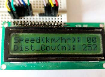
I have used a variable POT to adjust the Speed of the Motor for demonstration purpose. You can also use the same of find a real time application. If everything works as expected then you should be able to get the Velocity in Km/Hr and Distance covered in terms of meters as shown in the Video below.
Hope you enjoyed the project and got it working. If not you can use the comment section below or the forum to post your doubt.
Complete Project Code
/*
Speedometer and Odometer for PIC16F877A
 * Code by: B.Aswinth Raj
 * Dated: 27-07-2017
 * More details at: www.CircuitDigest.com
 */

#define _XTAL_FREQ 20000000
#define RS RD2
#define EN RD3
#define D4 RD4
#define D5 RD5
#define D6 RD6
#define D7 RD7

#include <xc.h>

#pragma config FOSC = HS        // Oscillator Selection bits (HS oscillator)
#pragma config WDTE = OFF       // Watchdog Timer Enable bit (WDT disabled)
#pragma config PWRTE = ON       // Power-up Timer Enable bit (PWRT enabled)
#pragma config BOREN = ON       // Brown-out Reset Enable bit (BOR enabled)
#pragma config LVP = OFF        // Low-Voltage (Single-Supply) In-Circuit Serial Programming Enable bit (RB3 is digital I/O, HV on MCLR must be used for programming)
#pragma config CPD = OFF        // Data EEPROM Memory Code Protection bit (Data EEPROM code protection off)
#pragma config WRT = OFF        // Flash Program Memory Write Enable bits (Write protection off; all program memory may be written to by EECON control)
#pragma config CP = OFF         // Flash Program Memory Code Protection bit (Code protection off)

int speed =0;
int milli_sec=0;
int rpm=0;
int c1,c2,c3;
int d1,d2,d3;
int distance;

//LCD Functions Developed by Circuit Digest.
void Lcd_SetBit(char data_bit) //Based on the Hex value Set the Bits of the Data Lines
{
if(data_bit& 1)
D4 = 1;
else
D4 = 0;

if(data_bit& 2)
D5 = 1;
else
D5 = 0;

if(data_bit& 4)
D6 = 1;
else
D6 = 0;

if(data_bit& 8)
D7 = 1;
else
D7 = 0;
}

void Lcd_Cmd(char a)
{
RS = 0;
Lcd_SetBit(a); //Incoming Hex value
EN  = 1;
        __delay_ms(4);
        EN  = 0;
}

void Lcd_Clear()
{
Lcd_Cmd(0); //Clear the LCD
Lcd_Cmd(1); //Move the curser to first position
}

void Lcd_Set_Cursor(char a, char b)
{
char temp,z,y;
if(a== 1)
{
 temp = 0x80 + b - 1; //80H is used to move the curser
z = temp>>4; //Lower 8-bits
y = temp & 0x0F; //Upper 8-bits
Lcd_Cmd(z); //Set Row
Lcd_Cmd(y); //Set Column
}
else if(a== 2)
{
temp = 0xC0 + b - 1;
z = temp>>4; //Lower 8-bits
y = temp & 0x0F; //Upper 8-bits
Lcd_Cmd(z); //Set Row
Lcd_Cmd(y); //Set Column
}
}

void Lcd_Start()
{
  Lcd_SetBit(0x00);
  for(int i=1065244; i<=0; i--)  NOP();
  Lcd_Cmd(0x03);
__delay_ms(5);
  Lcd_Cmd(0x03);
__delay_ms(11);
  Lcd_Cmd(0x03);
  Lcd_Cmd(0x02); //02H is used for Return home -> Clears the RAM and initializes the LCD
  Lcd_Cmd(0x02); //02H is used for Return home -> Clears the RAM and initializes the LCD
  Lcd_Cmd(0x08); //Select Row 1
  Lcd_Cmd(0x00); //Clear Row 1 Display
  Lcd_Cmd(0x0C); //Select Row 2
  Lcd_Cmd(0x00); //Clear Row 2 Display
  Lcd_Cmd(0x06);
}

void Lcd_Print_Char(char data)  //Send 8-bits through 4-bit mode
{
   char Lower_Nibble,Upper_Nibble;
   Lower_Nibble = data&0x0F;
   Upper_Nibble = data&0xF0;
   RS = 1;             // => RS = 1
   Lcd_SetBit(Upper_Nibble>>4);             //Send upper half by shifting by 4
   EN = 1;
   for(int i=2130483; i<=0; i--)  NOP();
   EN = 0;
   Lcd_SetBit(Lower_Nibble); //Send Lower half
   EN = 1;
   for(int i=2130483; i<=0; i--)  NOP();
   EN = 0;
}

void Lcd_Print_String(char *a)
{
int i;
for(i=0;a[i]!='\0';i++)
  Lcd_Print_Char(a[i]);  //Split the string using pointers and call the Char function
}
/*****End of LCD Functions*****/

/****Interrupt function ****/
void interrupt speed_isr()
{
        if(TMR0IF==1) // Timer has overflown
    {
        TMR0IF=0;       // Clear timer interrupt flag
         milli_sec++;
    }

        if (INTF==1)
        {
           rpm = (1000/milli_sec) * 60;
           speed = 0.3 * rpm * 0.37699; // (Assuming the wheel radius to be 30cm)
           INTF = 0;          // clear the interrupt flag
            milli_sec=0;
            distance= distance+028.2;
        }
}
/****End of Interrupt Function****/

int main()
{
    TRISD = 0x00; //PORTD declared as output for interfacing LCD
    TRISB0 = 1;        //DEfine the RB0 pin as input to use as interrupt pin
    OPTION_REG = 0b00000101;  // Timer0 with external freq and 64 as prescalar // Also Enables PULL UPs
    TMR0=100;       // Load the time value for 1ms; delayValue can be between 0-256 only
    TMR0IE=1;       //Enable timer interrupt bit in PIE1 register
    GIE=1;          //Enable Global Interrupt
    PEIE=1;         //Enable the Peripheral Interrupt
    INTE = 1;          //Enable RB0 as external Interrupt pin
    Lcd_Start();

    while(1)
    {
        c1 = (speed/100)%10;
        c2 = (speed/10)%10;
        c3 = (speed/1)%10;
        d1 = (distance/100)%10;
        d2 = (distance/10)%10;
        d3 = (distance/1)%10;

        if (milli_sec>1000)
        {
            speed=0;
        }
        Lcd_Set_Cursor(1,1);
        Lcd_Print_String("Speed(km/hr): ");
        Lcd_Print_Char(c1+'0');
        Lcd_Print_Char(c2+'0');
        Lcd_Print_Char(c3+'0');
        Lcd_Set_Cursor(2,1);
        Lcd_Print_String("Dist_Cov(m): ");
        Lcd_Print_Char(d1+'0');
        Lcd_Print_Char(d2+'0');
        Lcd_Print_Char(d3+'0');
    }
    return 0;
}
Comments
Can you please give me the
Can you please give me the hex code of your c file
motorcycel digital speedmeter
16f1946 circuit diagram and data in or data out pin number and mamory flash system
Technical difficulty
Hey Ashwin, I was wondering if this project is viable in real life application or not. because there we have tire is connected to bike with iron type material instead of plastic material.
Yes its very much possible to
Yes its very much possible to use this in real time. I have seen this concept being used in cycles speedometer kits. You can also buy one from ebay. I am sure it would also work for a bike be it plastic or metal
asking of help
before thanks you for the project we have given us completly.now i wish if it is possible having the code in asm .thank you
correction in speedometer circuit using pic calculation
The distance covered is calculated using circumference whose formula is 2*pi*r not pi*r*r therefore the disance covered should be 1.884m
you are correct this is
you are correct this is mathematic mistake
Which power supply is needed
Which power supply is needed ? 5v or 12v ?
error in the program
I want to edit the program but I can not create an old hex file
It shows me a line in (#include <xc.h>) where this file exists
If you delete it, the error appears at d4
Note that I use the micr c of Virgin 6.6.1. I also tried the hex file on the simulation program and it works well but the distance is up to 998 and starting from the first, what is the solution to make the distance meter reach more than this and how can I keep it With this value even after the power outage and when the operation again follows the count after the last number
thank you very much
Please use MPLAPX with XC8
Please use MPLAPX with XC8 compiler. You cannot use mickroC with this program
errors in the program
can you please compile once more the program,as there are errors in the lcd fuctions and interrupt fuctions
sir can I ask why rpm =
sir can I ask why rpm = (1000/milli_sec) * 60; what (1000) stands for. Can i use this algorithm to calculate speed in the interrupt: SPEED=(3600*2*PI*0.3)/milli_sec; /////0.3m radius, 3600 to exchange m/ms to km/h
1000 stand to convert mili
1000 stand to convert mili-second to second. And 60 is to convert seconds to minutes
dont miss 1000 to convert milisecond into second
Mainly LCD errors & some other errors
Haii aswinth
Iam USING mplabx v3.35& xc8 compiler v1.45
Iam getting so many errors regarding LCD commands&
int c1,c2,c3,int distance,int d1,int d2,int d3
I checked all ur tutorials interfacing LCD,
In that no code is bulid without errors.
Could you please give me any suggestions to overcome all errors.
Errors are appearing as
->Warning:(373 ) implicit signed to unsigned conversion
->Arithmetic overflow in constant expression
->Illegal conversion between pointer variables
can i get the hex file ..plz
can i get the hex file ..plz.its urgent
how the value is obtained
Velocity = (RPM (diameter * Pi) / 60)
v= radius_of_wheel * rpm * 0.37699
how the value 0.37699 is obtained if, v = (RPM * 2R * 3.14) / 60
= RPM * R * 0.104
frequency please? at what
frequency please? at what frequency microcontroller will run the hex file?
Value 0.37699
How the value 0.37699 obtained? and why RPM is (1000/TT)*60 what this 1000 means or stands for?
Velocity = (RPM (diameter *
Velocity = (RPM (diameter * Pi) / 60)
v= radius_of_wheel * rpm * 0.37699
how the value 0.37699 is obtained if, v = (RPM * 2R * 3.14) / 60
= RPM * R * 0.104 m/s
= RPM * R * 0.376 km/hr
1000 is to convert milisecond
1000 is to convert milisecond to second and 60 is to convert it to minute
Can you please provide a
Can you please provide a mikroC code or hex file of this code.
MikroC code would be preferred.
Thank You
sir,how i make a digital
sir,how i make a digital speedmetter circuit without using ardiuno or mcu
if you want to make speed
if you want to make speed meter whithout arduino or mcu , at least you need a counter/timer unless you cannot make it
hi iam try to copy paste and
hi iam try to copy paste and add some but not compile ineed help to get it
#define _XTAL_FREQ 20000000
#define RS RD2
#define EN RD3
#define D4 RD4
#define D5 RD5
#define D6 RD6
#define D7 RD7
#pragma config FOSC = HS // Oscillator Selection bits (HS oscillator)
#pragma config WDTE = OFF // Watchdog Timer Enable bit (WDT disabled)
#pragma config PWRTE = ON // Power-up Timer Enable bit (PWRT enabled)
#pragma config BOREN = ON // Brown-out Reset Enable bit (BOR enabled)
#pragma config LVP = OFF // Low-Voltage (Single-Supply) In-Circuit Serial Programming Enable bit (RB3 is digital I/O, HV on MCLR must be used for programming)
#pragma config CPD = OFF // Data EEPROM Memory Code Protection bit (Data EEPROM code protection off)
#pragma config WRT = OFF // Flash Program Memory Write Enable bits (Write protection off; all program memory may be written to by EECON control)
#pragma config CP = OFF // Flash Program Memory Code Protection bit (Code protection off)
char data;
int speed =0;
int milli_sec=0;
int rpm=0;
int c1,c2,c3;
int d1,d2,d3;
int distance;
unsigned int i=1065244 ;
//LCD Functions Developed by Circuit Digest.
void Lcd_SetBit(char data_bit) //Based on the Hex value Set the Bits of the Data Lines
{
if(data_bit& 1)
PORTD.F4 = 1;
else
PORTD.F4 = 0;
if(data_bit& 2)
PORTD.F5 = 1;
else
PORTD.F5 = 0;
if(data_bit& 4)
PORTD.F6 = 1;
else
PORTD.F6 = 0;
if(data_bit& 8)
PORTD.F7 = 1;
else
PORTD.F7 = 0;
}
void Lcd (char a)
{
PORTD.F2 = 0;
Lcd_SetBit(a); //Incoming Hex value
PORTD.F3 = 1;
delay_ms(4);
PORTD.F3 = 0;
}
void Lcd_Clear()
{
Lcd_Cmd(0); //Clear the LCD
Lcd_Cmd(1); //Move the curser to first position
}
void Lcd_Set_Cursor(char a, char b)
{
char temp,z,y;
if(a== 1)
{
temp = 0x80 + b - 1; //80H is used to move the curser
z = temp>>4; //Lower 8-bits
y = temp & 0x0F; //Upper 8-bits
Lcd_Cmd(z); //Set Row
Lcd_Cmd(y); //Set Column
}
else if(a== 2)
{
temp = 0xC0 + b - 1;
z = temp>>4; //Lower 8-bits
y = temp & 0x0F; //Upper 8-bits
Lcd_Cmd(z); //Set Row
Lcd_Cmd(y); //Set Column
}
}
void Lcd_Start()
{
Lcd_SetBit(0x00);
for( i<=1065244; i<=0; i--)NOP();
Lcd_Cmd(0x03);
delay_ms(5);
Lcd_Cmd(0x03);
delay_ms(11);
Lcd_Cmd(0x03);
Lcd_Cmd(0x02); //02H is used for Return home -> Clears the RAM and initializes the LCD
Lcd_Cmd(0x02); //02H is used for Return home -> Clears the RAM and initializes the LCD
Lcd_Cmd(0x08); //Select Row 1
Lcd_Cmd(0x00); //Clear Row 1 Display
Lcd_Cmd(0x0C); //Select Row 2
Lcd_Cmd(0x00); //Clear Row 2 Display
Lcd_Cmd(0x06);
}
void Lcd_Print_Char(char data ) //Send 8-bits through 4-bit mode
{
char Lower_Nibble,Upper_Nibble;
Lower_Nibble = data&0x0F;
Upper_Nibble = data&0xF0;
RS = 1; // => RS = 1
Lcd_SetBit(Upper_Nibble>>4); //Send upper half by shifting by 4
EN = 1;
for(int i=2130483; i<=0; i--)
NOP();
EN = 0;
Lcd_SetBit(Lower_Nibble); //Send Lower half
EN = 1;
for(int i=2130483; i<=0; i--)
NOP();
EN = 0;
}
void Lcd_Print_String(char *a)
{
int i;
for(i=0;a[i]!='\0';i++)
Lcd_Print_Char(a[i]); //Split the string using pointers and call the Char function
}
/*****End of LCD Functions*****/
/****Interrupt function ****/
void interrupt speed_isr()
{
if(TMR0IF==1) // Timer has overflown
{
TMR0IF=0; // Clear timer interrupt flag
milli_sec++;
}
if (INTF==1)
{
rpm = (1000/milli_sec) * 60;
speed = 0.3 * rpm * 0.37699; // (Assuming the wheel radius to be 30cm)
INTF = 0; // clear the interrupt flag
milli_sec=0;
distance= distance+028.2;
}
}
/****End of Interrupt Function****/
int main()
{
TRISD = 0x00; //PORTD declared as output for interfacing LCD
TRISB0 = 1; //DEfine the RB0 pin as input to use as interrupt pin
OPTION_REG = 0b00000101; // Timer0 with external freq and 64 as prescalar // Also Enables PULL UPs
TMR0=100; // Load the time value for 1ms; delayValue can be between 0-256 only
TMR0IE=1; //Enable timer interrupt bit in PIE1 register
GIE=1; //Enable Global Interrupt
PEIE=1; //Enable the Peripheral Interrupt
INTE = 1; //Enable RB0 as external Interrupt pin
Lcd_Start();
while(1)
{
c1 = (speed/100)%10;
c2 = (speed/10)%10;
c3 = (speed/1)%10;
d1 = (distance/100)%10;
d2 = (distance/10)%10;
d3 = (distance/1)%10;
if (milli_sec>1000)
{
speed=0;
}
Lcd_Set_Cursor(1,1);
Lcd_Print_String("Speed(km/hr): ");
Lcd_Print_Char(c1+'0');
Lcd_Print_Char(c2+'0');
Lcd_Print_Char(c3+'0');
Lcd_Set_Cursor(2,1);
Lcd_Print_String("Dist_Cov(m): ");
Lcd_Print_Char(d1+'0');
Lcd_Print_Char(d2+'0');
Lcd_Print_Char(d3+'0');
}
return 0;
}
could someone clarify the
could someone clarify the specifications of components?
Please tell me for which
Please tell me for which component you need specifications ?
Sir, I read again and again…
Sir, I read again and again the code and the comments but still cannot figure how you got the value of 0.37699 in "The value is also multiplied with 0.37699". Please explain with details or if possible with taking circumference instead of radius. Thanks

there is some error in the code .... iam not getting the output.. pls kindly help me