

In this tutorial we will learn how easy it is to save data using the EEPROM present in the PIC16F877A Microcontroller. In most real time projects we might have to save some data which should not be erased even when the power is turned off. This might sound like a complicated process, but with the help of XC8 Compiler this task can be done by just using a single line of code. If the data is large in terms of Mega bytes then we can interface a storage device like an SD card and store those data on them. But we can avoid those tiring process if the data is small, we can simply use the EEPROM present in the PIC Microcontroller to save our data and retrieve it at anytime we want.
This PIC EEPROM tutorial is a part of a sequence of PIC Microcontroller Tutorials in which we started from a very basic level. If you haven’t learnt the previous tutorials then it would be better to have a look at them now, because this tutorial assumes that you are familiar with Interfacing LCD with PIC Microcontroller and Using ADC with PIC Microcontroller.
EEPROM in PIC16F877A:
EEPROM stand for “Electronically Erasable and Programmable Read Only Memory”. As the name suggests it is a memory present inside the PIC Microcontroller in which we can write/read data by programming it to do so. The data saved in this will be erased only if it is mentioned to do so in the program. The amount of storage space available in EEPROM varies upon each microcontroller; the details will be given in Datasheet as usual. In our case for PIC16F877A the available space is 256 bytes as mentioned in its specification datasheet. Now let us see how we can use these 256 bytes to read/write data by using a simple experimental setup.
Circuit Diagram and Explanation:

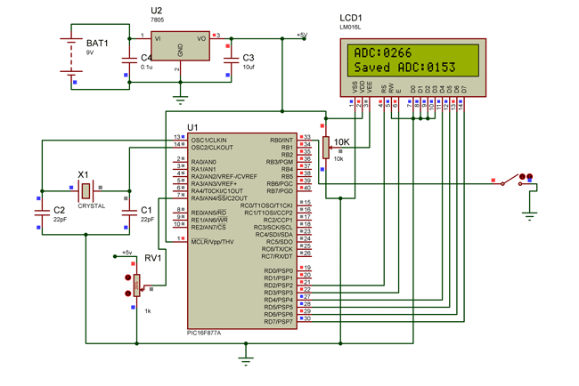
The circuit diagram for the project is shown above. We have interfaced an LCD to visualize the data getting saved and retrieved. A normal potentiometer is connected to AN4 Analog channel so feed in variable voltage, this variable voltage will be used as the data to be saved in the EEPROM. We have also used a push button on RB0, when this button is pressed the data from the Analog channel will be saved in the EEPROM.
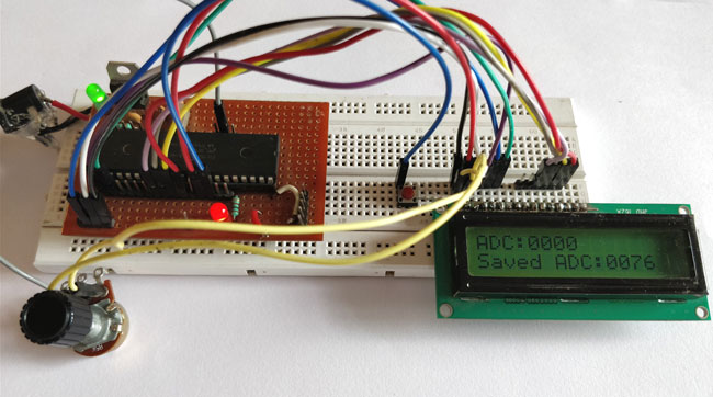
This connection can be made on a breadboard. The pinouts of the PIC Microcontroller is shown in the table below.
|
S.No: |
Pin Number |
Pin Name |
Connected to |
|
1 |
21 |
RD2 |
RS of LCD |
|
2 |
22 |
RD3 |
E of LCD |
|
3 |
27 |
RD4 |
D4 of LCD |
|
4 |
28 |
RD5 |
D5 of LCD |
|
5 |
29 |
RD6 |
D6 of LCD |
|
6 |
30 |
RD7 |
D7 of LCD |
|
7 |
33 |
RBO/INT |
Push button |
|
8 |
7 |
AN4 |
Potentiometer |
Simulation of Using PIC EEPROM :
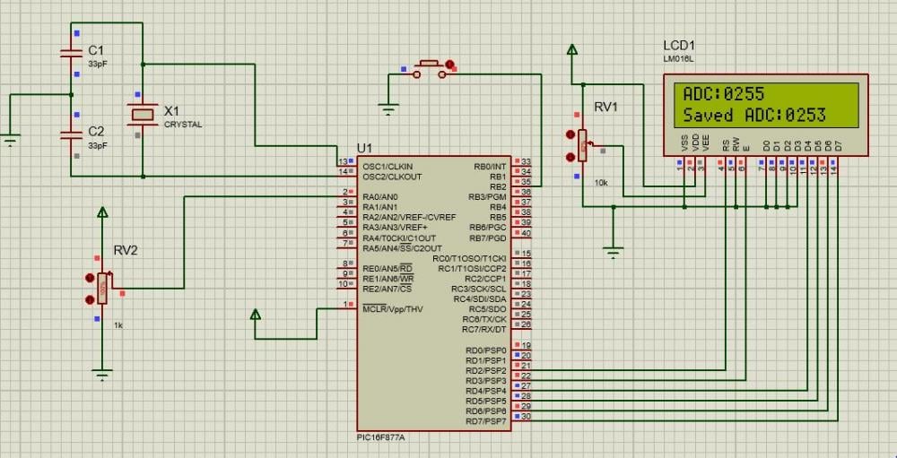
This project also involves a Simulation designed using Proteus, using which we can simulate the working of the project without any hardware. The program for this simulation is given at the end of this tutorial. You can simply use the Hex file from here and simulate the whole process.
During simulation you can visualize the Current ADC value and data saved in the EEPROM on the LCD screen. To save the current ADC value into the EEPROM simply press the switch connected to RB0 and it will be saved. A snapshot of the simulation is shown below.
Programming PIC for EEPROM:
The complete code for this tutorial is given at the end of this tutorial. In our program we have to read the Values from ADC module and when a button is pressed we have to save that value in our EEPROM. Since we have already learnt about ADCs and LCD interfacing, I will further explain the code to save and retrieve data from EEPROM.
According to Datasheet “These devices have 4 or 8K words of program Flash, with an address range from 0000h to 1FFFh for the PIC16F877A”. This means that each EEPROM storage space has an address through which it can be accessed and in our MCU the address starts from 0000h to 1FFFh.
To save a data inside a particular EEPROM address simply use the below line.
eeprom_write(0,adc);
Here “adc” is a variable of type integer in which the data to be saved is present. And “0” is the address of the EEPROM on which our data is saved. The syntax “eeprom_write” is provided by our XC8 complier hence the registers will be automatically taken care by the compiler.
To retrieve a data that is already stored in EEPROM and save it to a variable the following line of code can be used.
Sadc = (int)eeprom_read(0);
Here, “Sadc” is the variable in which the data from the EEPROM will be saved. And “0” is the address of EEPROM from which we are retrieving the data. The syntax “eeprom_read” is provided by our XC8 complier hence the registers will be automatically taken care by the compiler. The data saved in EEPROM will be in hexadecimal type. Hence we convert them to integer type by prefixing a (int) before the syntax.
Working:
Once we understand how the code works and get ready with the hardware we can test out code. Upload the code to your PIC Microcontroller and power the set-up. If everything is working as expected then you should see the current ADC values displayed in the LCD. You can now press the button to save the ADC value to the EEPROM. Now you check if the value is saved by turning off the whole system and turning it on again. When powered on you should see the previously saved value on the LCD screen.
The complete working of this project to use PIC Microcontroller EEPROM is shown in the video below. Hope you understood the tutorial and enjoyed doing it. If you have any doubts you can write them on the comment section below or post them on our forums.
Complete Project Code
#define _XTAL_FREQ 20000000
#define RS RD2
#define EN RD3
#define D4 RD4
#define D5 RD5
#define D6 RD6
#define D7 RD7

#include <xc.h>

#pragma config FOSC = HS        // Oscillator Selection bits (HS oscillator)
#pragma config WDTE = OFF       // Watchdog Timer Enable bit (WDT disabled)
#pragma config PWRTE = ON       // Power-up Timer Enable bit (PWRT enabled)
#pragma config BOREN = ON       // Brown-out Reset Enable bit (BOR enabled)
#pragma config LVP = OFF        // Low-Voltage (Single-Supply) In-Circuit Serial Programming Enable bit (RB3 is digital I/O, HV on MCLR must be used for programming)
#pragma config CPD = OFF        // Data EEPROM Memory Code Protection bit (Data EEPROM code protection off)
#pragma config WRT = OFF        // Flash Program Memory Write Enable bits (Write protection off; all program memory may be written to by EECON control)
#pragma config CP = OFF         // Flash Program Memory Code Protection bit (Code protection off)


//LCD Functions Developed by Circuit Digest.
void Lcd_SetBit(char data_bit) //Based on the Hex value Set the Bits of the Data Lines
{
if(data_bit& 1)
D4 = 1;
else
D4 = 0;

if(data_bit& 2)
D5 = 1;
else
D5 = 0;

if(data_bit& 4)
D6 = 1;
else
D6 = 0;

if(data_bit& 8)
D7 = 1;
else
D7 = 0;
}

void Lcd_Cmd(char a)
{
RS = 0;
Lcd_SetBit(a); //Incoming Hex value
EN  = 1;
        __delay_ms(4);
        EN  = 0;
}

void Lcd_Clear()
{
Lcd_Cmd(0); //Clear the LCD
Lcd_Cmd(1); //Move the curser to first position
}

void Lcd_Set_Cursor(char a, char b)
{
char temp,z,y;
if(a== 1)
{
 temp = 0x80 + b - 1; //80H is used to move the curser
z = temp>>4; //Lower 8-bits
y = temp & 0x0F; //Upper 8-bits
Lcd_Cmd(z); //Set Row
Lcd_Cmd(y); //Set Column
}
else if(a== 2)
{
temp = 0xC0 + b - 1;
z = temp>>4; //Lower 8-bits
y = temp & 0x0F; //Upper 8-bits
Lcd_Cmd(z); //Set Row
Lcd_Cmd(y); //Set Column
}
}

void Lcd_Start()
{
  Lcd_SetBit(0x00);
  for(int i=1065244; i<=0; i--)  NOP();
  Lcd_Cmd(0x03);
__delay_ms(5);
  Lcd_Cmd(0x03);
__delay_ms(11);
  Lcd_Cmd(0x03);
  Lcd_Cmd(0x02); //02H is used for Return home -> Clears the RAM and initializes the LCD
  Lcd_Cmd(0x02); //02H is used for Return home -> Clears the RAM and initializes the LCD
  Lcd_Cmd(0x08); //Select Row 1
  Lcd_Cmd(0x00); //Clear Row 1 Display
  Lcd_Cmd(0x0C); //Select Row 2
  Lcd_Cmd(0x00); //Clear Row 2 Display
  Lcd_Cmd(0x06);
}

void Lcd_Print_Char(char data)  //Send 8-bits through 4-bit mode
{
   char Lower_Nibble,Upper_Nibble;
   Lower_Nibble = data&0x0F;
   Upper_Nibble = data&0xF0;
   RS = 1;             // => RS = 1
   Lcd_SetBit(Upper_Nibble>>4);             //Send upper half by shifting by 4
   EN = 1;
   for(int i=2130483; i<=0; i--)  NOP();
   EN = 0;
   Lcd_SetBit(Lower_Nibble); //Send Lower half
   EN = 1;
   for(int i=2130483; i<=0; i--)  NOP();
   EN = 0;
}

void Lcd_Print_String(char *a)
{
int i;
for(i=0;a[i]!='\0';i++)
  Lcd_Print_Char(a[i]);  //Split the string using pointers and call the Char function
}
/*****End of LCD Functions*****/


//**ADC FUnctions***//
void ADC_Initialize()
{
  ADCON0 = 0b01000001; //ADC ON and Fosc/16 is selected
  ADCON1 = 0b11000000; // Internal reference voltage is selected
}

unsigned int ADC_Read(unsigned char channel)
{
  ADCON0 &= 0x11000101; //Clearing the Channel Selection Bits
  ADCON0 |= channel<<3; //Setting the required Bits
  __delay_ms(2); //Acquisition time to charge hold capacitor
  GO_nDONE = 1; //Initializes A/D Conversion
  while(GO_nDONE); //Wait for A/D Conversion to complete
  return ((ADRESH<<8)+ADRESL); //Returns Result
}
//***End of ADC Functions***//

int main()
{
    int adc=0; //Variable to read ADC value
    int a1,a2,a3,a4; //Variable to split ADC value into char

    int Sadc=0; //Variable to read ADC value
    int Sa1,Sa2,Sa3,Sa4; //Variable to split ADC value into char

    TRISD = 0x00; //PORTD declared as output for interfacing LCD
    TRISA4 =1; //AN4 declared as input
    TRISB0  = 1;
    OPTION_REG=0b00000000;
    ADC_Initialize();
    Lcd_Start();
    Lcd_Clear();

    while(1)
    {
        adc=ADC_Read(4); //Read ADC

         //**Display ADC**//
        a1 = (adc/1000)%10;
        a2 = (adc/100)%10;
        a3 = (adc/10)%10;
        a4 = (adc/1)%10;
        Lcd_Set_Cursor(1,1);
        Lcd_Print_String("ADC:");
        Lcd_Print_Char(a1+'0');
        Lcd_Print_Char(a2+'0');
        Lcd_Print_Char(a3+'0');
        Lcd_Print_Char(a4+'0');

      //**Display SADC**//
        Sa1 = (Sadc/1000)%10;
        Sa2 = (Sadc/100)%10;
        Sa3 = (Sadc/10)%10;
        Sa4 = (Sadc/1)%10;
        Lcd_Set_Cursor(2,1);
        Lcd_Print_String("Saved ADC:");
        Lcd_Print_Char(Sa1+'0');
        Lcd_Print_Char(Sa2+'0');
        Lcd_Print_Char(Sa3+'0');
        Lcd_Print_Char(Sa4+'0');
        /*These devices have 4 or 8K words of
          program Flash, with an address range from 0000h to
          1FFFh for the PIC16F877A*/

        if (RB0==0)
        {eeprom_write(0,adc);}

        Sadc = (int)eeprom_read(0);

        Lcd_Set_Cursor(1,1);
        Lcd_Print_String("ADC:");

    }
    return 0;
}
Comments
To save a data inside a
To save a data inside a particular EEPROM address simply use the below line.
eeprom_write(0,adc);
Here “adc” is a variable of type integer in which the data to be saved is present. And “0” is the address of the EEPROM on which our data is saved. The syntax “eeprom_write” is provided by our XC8 complier hence the registers will be automatically taken care by the compiler.
To retrieve a data that is already stored in EEPROM and save it to a variable the following line of code can be used.
Sadc = (int)eeprom_read(0);
Here, “Sadc” is the variable in which the data from the EEPROM will be saved. And “0” is the address of EEPROM from which we are retrieving the data. The syntax “eeprom_read” is provided by our XC8 complier hence the registers will be automatically taken care by the compiler. The data saved in EEPROM will be in hexadecimal type. Hence we convert them to integer type by prefixing a (int) before the syntax.
19/03/2020
I can't save data from 256 to 1024
Example: I save number 256 but EEPROM save 0000
same here quanghhuy
same here quanghhuy
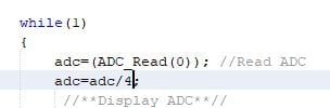
ADC register is 10 bit and can save from 0 to 1023, but EEPROM storage is 8 bit and can only save from 0 to 255. after 256 it start from zero
The solution i found is to
The solution i found is to devide adc by 4 so the adc value start from 0 to 255 which is the mazimum value we can save in EEPROM
Yes this is exactly the way
Yes this is exactly the way to do it. You can use bit shifting if you wanna make things more effeciant, but your technique should also work well in most cases
Hi mister , can I use the
Hi mister , can I use the copy the code in the editor mikroC

Can you provide the details about how the data are saved by pressing the push button? and also, the connection of push button is not clear here.Can you please provide these?