

The mileage and performance of an Electric Vehicle depends on the capacity and efficiency of its Battery Pack. To maintain the battery pack in full health is the responsibility of the Battery Management System (BMS). A BMS is a sophisticated unit in an EV which does a lot of activity like monitoring the cells, balancing them and even protecting them from temperature changes. We have already learnt enough of it in this Battery Management System article, so check them out if you are new here.
To do anything, the first step for the BMS would be to know the current status of the cells in the Lithium battery pack. This is done by measuring the voltage and current (sometimes temperature also) of the cells in the pack. Only with these two values the BMS could calculate the SOC or SOH and perform cell balancing etc. So measuring the voltage and current of cell is vital for any BMS circuit, be it a simple power bank or laptop battery or as complicated pack as EV/Solar batteries.
In this article we will learn how we can measure the individual cell voltage of the cells used in a Lithium battery pack. For the sake of this project we will use four lithium 18650 cells connected in series to form a battery pack and design a simple circuit using op-amps to measure the individual cell voltages and display it on a LCD screen using Arduino.
Measuring Individual Cell Voltage in a Series Battery Stack
The problem with measuring individual cell voltage in a pack of series connected battery is that, the reference point remains the same. The below picture illustrates the same
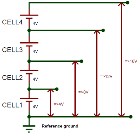
For simplicity let us assume that all four cells are at a voltage level of 4V as shown above. Now if we use a microcontroller like Arduino to measure the cell voltage, we will have no problem in measuring the voltage of 1st cell since it has the other end connected to ground. But, for the other cells we have to measure the voltage of that cell along with the previous cells, for instance when we measure the voltage of 4th cell we will measure the voltage of all four cells together. This is because the reference point cannot be changed from ground.
So we need to introduce some extra circuit here which could help us measure the individual voltages. At crude way is to use a potential divider to map down the voltage levels and then measure them, but this method will reduce the resolution of the read value to more than 0.1V. Hence in this tutorial we will use the Op-Amp Differential Circuit to measure the difference between each cell terminals to measure individual voltage.
Differential Circuit to measure individual Cell voltage
We already know an Op-Amp when working as a differential amplifier gives the difference between the two voltage values provided to its inverting and non-inverting pin. So for our purpose of measuring 4 cell voltages we need three differential op-amps as shown below.
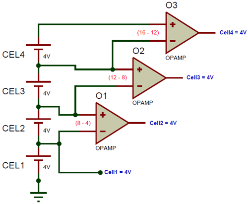
Note that this image is only for representation; the actual circuit needs more components and will be discussed later in this article. The first op-amp O1 measures the voltage of the 2nd cell by calculating the difference between 2nd cell terminal and 1st cell terminal that is (8-4). Similarly the Op-amp O2 and O3 measures the 3rd and 4th cell voltage respectively. We have not used an op-amp for the 1st cell since it could be measured directly.
Circuit Diagram
The complete circuit diagram for monitoring Multicell voltage in Lithium Battery Pack is given below. The circuit was designed using EasyEDA and we will use the same to fabricate our PCB also.

As you can see we have two Quad package Rail to Rail High voltage op-amp OPA4197 in our circuit both powered by the total pack voltage. One IC (U1) is used a make buffer circuit aka voltage follower while the other IC (U2) is used to form the differential amplifier circuit. A buffer circuit is required to prevent any of the cells from getting loaded individually, which is no current should be consumed from a single cell but only form the pack as a whole. Since the buffer circuit has very high input impedance we can use to read the voltage from the cell without drawing power from it.
All the four op-amps in the IC U1 is used to buffer the voltage of the four cells respectively. The input voltages from the cells are labeled from B1+ to B4+ and the buffered output voltage is labeled from B1_Out to B4_Out. This buffered voltage is then sent to the differentia amplifier to measure the individual cell voltage as discussed above. The value of all the resistor is set to 1K since the gain of the differential amplifier is set to unity. You can use any resistor value but they all should be of the same value, except for the resistors R13 and R14. These two resistors form a potential divider to measure the pack voltage of the battery so that we can compare it with the sum of measured cell voltages.
Rail to Rail, high voltage Op-Amp
The above circuit requires you to use a Rail to Rail high voltage op-amp like OPA4197 because of two reasons. Both the Op-Amp IC operate at with the pack voltage that is a maximum of (4.3*4) 17.2V, hence the Op-amp should be capable of handling high voltages. Also since we are using a buffer circuit, the output of the buffer should be equal to pack voltage for the 4th cell terminal, meaning the output voltage should be equal to operating voltage of the op-amp hence we need to use a Rail to Rail op-amp
If you cannot find a rail to rail op-amp, you can replace the IC with simple LM324. This IC can handle high voltage but cannot act as rail to rail, so you have to use a pull up resistor of 10k on the first pin of the U1 Op-Amp IC.
PCB Design and Fabrication using Easy EDA
Now that our circuit is ready, it is time to get it fabricated. Since the Op-Amp I am using is available only in SMD package I had to fabricate a PCB for my circuit. So, like always we have used the online EDA tool called EasyEDA to get our PCB fabricated because it is very convenient to use since it has a good collection of footprints and it is open-source.
After designing the PCB, we can order the PCB samples by their low cost PCB fabrication services. They also offer component sourcing service where they have a large stock of electronic components and users can order their required components along with the PCB order.
While designing your circuits and PCBs, you can also make your circuit and PCB designs public so that other users can copy or edit them and can take benefit from your work, we have also made our whole Circuit and PCB layouts public for this circuit, check the below link:
https://easyeda.com/CircuitDigest/Multicell-Voltage-measuring-for-BMS
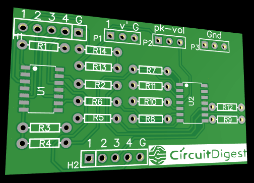
You can view any Layer (Top, Bottom, Topsilk, bottomsilk etc) of the PCB by selecting the layer form the ‘Layers’ Window. Recently they have also introduced a 3D view option so you can also view the Multicell voltage measuring PCB, on how it will look after fabrication using the 3D View button in EasyEDA:
Calculating and Ordering Samples online
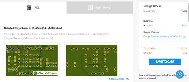
After completing the design of this Lithium cell Voltage measurement circuit, you can order the PCB through JLCPCB.com. To order the PCB from JLCPCB, you need Gerber File. To download Gerber files of your PCB just click the Generate Fabrication File button on EasyEDA editor page, then download the Gerber file from there or you can click on Order at JLCPCB as shown in below image. This will redirect you to JLCPCB.com, where you can select the number of PCBs you want to order, how many copper layers you need, the PCB thickness, copper weight, and even the PCB color, like the snapshot shown below:
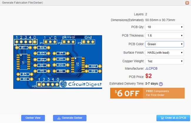
After clicking on order at JLCPCB button, it will take you to JLCPCB website where you can order any color PCB in very low rate which is $2 for all the colors. Their build time is also very less which is 48 hours with DHL delivery of 3-5 days, basically you will get your PCBs within a week of ordering. Moreover, they are also offering a $20 discount on shipping for your first order.
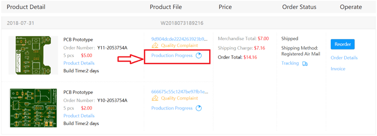
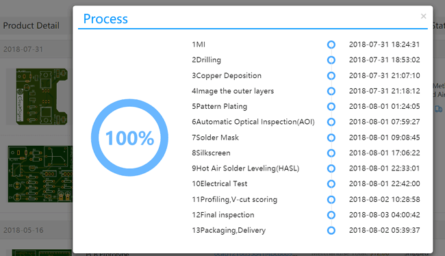
After ordering the PCB, you can check the Production Progress of your PCB with date and time. You check it by going on Account page and click on "Production Progress" link under the PCB like, shown in below image.
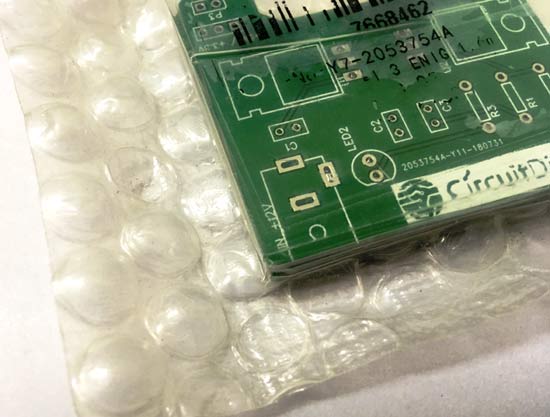
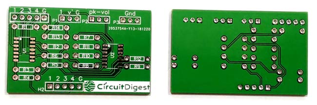
After few days of ordering PCB’s I got the PCB samples in nice packaging as shown in below pictures.

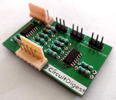
After making sure the tracks and footprints were correct. I proceeded with assembling the PCB, I used female headers to place the Arduino Nano and LCD so that I can remove them later if I need them for other projects. The completely soldered board looks like this below

Testing the Voltage Monitoring Circuit
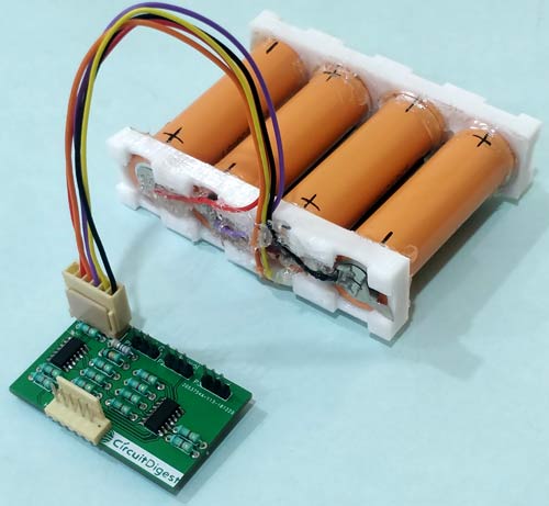
After soldering all the components, simply connect the battery pack to the H1 connector on the board. I have made use of connecting cables to makes sure I don’t change the connection in the future by accident. Be very careful about not connecting it in the wrong way as it could lead to short circuit and would damage the batteries or the circuit permanently. My PCB with the battery pack that I used for testing is shown below.
Now use the multimeter on the H2 terminal to measure the individual sell voltages. The terminal is marked with numbers to identify the cell voltage that is current being measured. With here we can conclude that the circuit is working. But to make it more interesting let us connect an LCD and use an Arduino to measure these voltage values and display it on the LCD screen.
Measuring the Lithium Cell Voltage Using Arduino
The circuit to connect the Arduino to our PCB is show below. It shows how to connect the Arduino Nano to LCD.
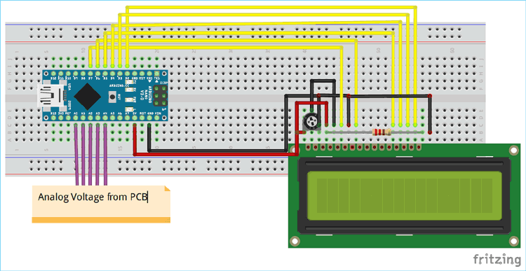
The header pin H2 on the PCB should be connected to the analog pins of the Arduino board as shown above. The analog pins A1 to A4 is used to measure the four cell voltages respectively, while the pin A0 is connected to header pin v’ of P1. This v’ pin can be used to measure the total pack voltage. We have also connected the 1st pin of P1 to the Vin pin of the Arduino and 3rd pin of P1 o the ground pin of Arduino to power the Arduino with the Battery pack.
We can write a program to measure all the four cell voltages and pack voltage of the battery pack and display it in the LCD. To make it more interesting I have also added all the four cell voltages and compared the value with the measured pack voltage to check how close we are actually measuring the voltage.
Programming the Arduino
The complete program can be found at the end of this page. The program is pretty simple, we simply use the analog read function to read the cell voltages using ADC module and display the calculate voltage value on the LCD using the LCD library.
  float Cell_1 = analogRead(A1) * (5.0 / 1023.0); //Measure 1st cell voltage
  lcd.print("C1:"); lcd.print(Cell_1);
In the above snippet we have measured the voltage of cell 1 and multiplied it with 5/1023 to convert the 0 to 1023 ADC value to actual 0 to 5V. We then display the calculated voltage value on the LCD. Similarly we do this for all the four cells and the total battery pack as well. We have also used the variable total voltage to sum up all the cell voltages and display it on the LCD like shown below.
  float Total_Voltage = Cell_1+Cell_2+Cell_3+Cell_4; //Add all the four measured voltage values
  lcd.print("Total:"); lcd.print(Total_Voltage);
Individual Cell Voltage Display Working
Once you are ready with the circuit and code, upload the code to the Arduino board and connect the power bank to the PCB. The LCD should now display the individual cell voltage of all the four cells like shown below.
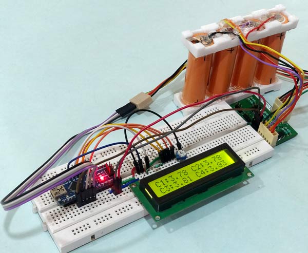
As you can see the voltage displayed for cell 1 to 4 is 3.78V, 3.78V, 3.82V and 3.84V respectively. So Then I used my multimeter to check the actual voltage of these cells which turned out to be a bit different the difference is tabulated below.
Measured Voltage | Actual Voltage |
3.78V | 3.78V |
3.78V | 3.78V |
3.82V | 3.81V |
3.84V | 3.82V |
As you can see we have getting accurate results for the cells one and two but there is an error as high as 20mV for cells 3 and 4. This is most likely to be expected for our design. Since we are using an op-amp differentiator circuit, the accuracy of the measured voltage will go down as the number of cells increase.
But this error is a fixed error and can be corrected in the program, by taking sample readings and adding a multiplier to correct the error. On the next LCD screen you can also see the sum of the measured voltage and the actual pack voltage that was measured through potential divider. The same is shown below.
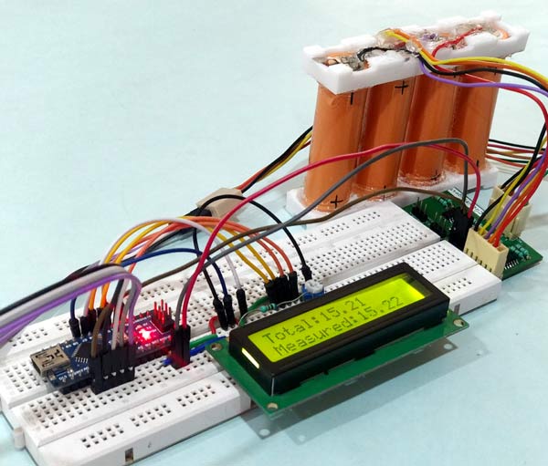
The sum of the voltages that was measured is 15.21V and the actual voltage measured through the A0 pin of Arduino turns out to be 15.22V. Thus the difference is 10mV which is not bad. While these type of circuit can be used to for lesser number of lees like in power banks or laptop batteries. The electric vehicle BMS uses special type of ICs like the LTC2943 because even an error of 10mV is not tolerable. Nevertheless we have learnt how to do it for small scale circuit where price is a constraint.
The complete working of the set-up can be found at the video linked below. Hope you enjoyed the project and learnt something useful from it. If you have any questions leave them in the comment section or use the forums for faster replies.
Complete Project Code
/*Measuring Indivudual Cell Voltage for BMS
 *Author: B.Aswinth Raj
 *Dated: 21-1-2019
 */
#include <LiquidCrystal.h> //Librarey for LCD display
const int rs = 7, en = 6, d4 = 5, d5 = 4, d6 = 3, d7 = 2; //Mention the pin number for LCD connection
LiquidCrystal lcd(rs, en, d4, d5, d6, d7);

void setup() {
  lcd.begin(16, 2); //Initialise 16*2 LCD
  lcd.print("Voltage Monitor"); //Intro Message line 1
  lcd.setCursor(0, 1);
  lcd.print("    for EV    "); //Intro Message line 2
  delay(2000);
  lcd.clear();
}

void loop() {
  float Cell_1 = analogRead(A1) * (5.0 / 1023.0); //Measure 1st cell voltage
  lcd.print("C1:"); lcd.print(Cell_1);
  float Cell_2 = analogRead(A2) * (5.0 / 1023.0); //Measure 2nd cell voltage
  lcd.print(" C2:"); lcd.print(Cell_2);
  lcd.setCursor(0, 1);
  float Cell_3 = analogRead(A3) * (5.0 / 1023.0); //Measure 3rd cell voltage
  lcd.print("C3:"); lcd.print(Cell_3);

  float Cell_4 = analogRead(A4) * (5.0 / 1023.0); //Measure 4th cell voltage
  lcd.print(" C4:"); lcd.print(Cell_4);
  delay(4000);
  lcd.clear();
  float Total_Voltage = Cell_1+Cell_2+Cell_3+Cell_4; //Add all the four measured voltage values
  lcd.print("Total:"); lcd.print(Total_Voltage);

  lcd.setCursor(0, 1);
  float Pack_Voltage = analogRead(A0) * (5.0 / 1023.0) * 4.002; //Measure the total pack voltage
  lcd.print("Measured:"); lcd.print(Pack_Voltage);
  delay(2000);
  lcd.clear();
}
Comments
Hi, Very instructive! Can this be done with four positive ground 12 V batteries? What needs to change?
We can give maximum 5 volt input to arduino so if you want to use it for 12V battries then use voltage regulator for providing 5 V input to arduino you also need to change values in code also. bcoz you have to convert 5 V scale into 12V scale
Hi, the difference between 3.82v and 3.84v is 20mv not 200mv as stated in the article.
Hi, very useful, nicely explained. I would like to know, is it possible to modify this circuit for bigger battery pack, as 5s, 7s, or 10s, etc. Regards from Serbia.
Hi, what do you mean with LM324 "use a pull up resistor of 10k on the first pin of the U1 Op-Amp IC" ?
That means that we have to put a voltge divider (2x 10k) on each input? could you explain that?
Thanks
Hello, I'm here to ask about the use of LM324 instead of the OPA4197
Could you explain more about that "pull up 10K resistor onthe first pin of the U1 Op-Amp IC"?
I'm designing a circuit to monitor a 7s battery pack and would like to use 4 LM324, since I already have they, and thinking how to implement they with this 10K pull up resistor. do I need to connect it between every BX_OUT and the positive of the battery pack (like 29 volts)? Or it should be only one resistor between the B2_OUT and the positive of the battery? Or nothing of this two? Could you help me with that?
I replicate your circuit with the representation of the OpAmps, could you show me where to put the 10k resistor?

Dear Ashwinth,
Thanks for the Great Article
Could you please explain in more depth about difference in normal and rail to rail opamps and the exact modifications required in the circuit to use the LM324 instead of OPA4197 and the logic/reason behind the modification.
Thanks