

This is the third tutorial in the sequence of tutorials in which we are learning to program the MSP430G2 LaunchPad using the Energia IDE. In our previous tutorial, we learned how to control the Digital Input and Output pins on our MSP board. In this tutorial, we will learn how to interface an LCD with the board so that we can display useful information.
The LCD that we are using in this project is the most commonly used 16×2 Dot matrix LCD display a.k.an Alphanumeric Displays. Most of us would have come across this either through public PCOs or other electronics projects. A display like this will come in very handy for our future tutorials to display data and other debugging information. Interfacing this LCD with MSP430 is very easy, thanks to the library available. So let’s dive in!!
Materials Required:
- MSP430G2 LaunchPad from Texas Instruments
- 16×2 Dot matrix LCD display
- Connecting wires
- Energia IDE
Brief Intro to 16×2 Dot matrix LCD display:
As told earlier the Energia IDE provides a beautiful library which makes the interfacing a piece of cake and hence it’s not mandatory to know anything about the display module. But, would didn’t it be interesting to show what we are using!!
The name 16×2 implies that the display has 16 Columns and 2 Rows, which together (16*2) forms 32 boxes. One single box would look something like this in the picture below
![]()
A single box has 40 pixels (dots) with a matrix order of 5 Rows and 8 columns, these 40 pixels together forms one character. Similarly, 32 characters can be displayed using all the boxes. Now lets take a look at the pinouts.

The LCD has a total of 16 Pins, as shown above, they can be categorized into four groups like as follows
Source Pins (1, 2 and 3): These pins source the power and contrast level for the display
Control Pins (4, 5 and 6): These pins sets/controls the registers in the LCD interfacing IC (more this can be found in link below)
Data/Command Pins (7 to 14): These pins provide the data of what information should be displayed on the LCD.
LED pins (15 and 16): These pins are used to glow the backlight of LCD if needed (optional).
Out of all these 16 pins, only 10 pins are to be used mandatory for the proper working of the LCD if you want to know more about these LCD display jump to this LCD article.
Circuit Diagram and Connection:
The complete circuit diagram to interface a 16×2 Dot matrix LCD display with MSP430G2 is shown below.

One major constraint while interfacing these two is their operating voltages. The LCD display has an operating voltage of +5V while the MSP operates only with 3.6V. Lucky for us the data pin of LCD interface IC (HD44780U) has a wide operating voltage of 2.7V to 5.5V. So we have to worry only about the Vdd (pin 2) of the LCD while the data pins can work even with 3.6V.
The MSP430G2 board by default does not give you a +5V pin, but by we can do a small hack to get +5V from MSP430 using the USB port. If you take a close look near the USB port you can find a terminal called TP1, this terminal will give us +5v. All we have to do is to solder a small male header pin as shown below so that we can connect it to our LCD display.
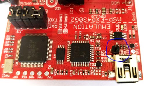
Note: Do not connect loads that might consume more than 50mA to this 5V pin s it might fry your USB port.
If you are not interested in soldering simply use any +5V regulated supply and power the LCD, in that case, make sure you connect the ground of your power supply to the ground of the MSP board.
Once you are done with the +5V pin connecting the other pins are pretty much straightforward. Now that our hardware is ready, let’s move on to the software part.
Programming MSP430 for LCD using Energia:
The complete program to interface an MSP430G2553 with LCD display is given at the end of this page. The code can be compiled, uploaded and used as such. In the following paragraphs, I will explain how the program works.
Before we proceed with explanation, we have to make a note of the pins that we are using. If you take a look the circuit diagram above and the MSP430 pin-out diagram below

You can conclude that we have connected the LCD as per the following table
|
LCD pin name |
Connected to |
|
Vss |
Ground |
|
Vdd |
+5V USB pin |
|
Rs |
Pin 2 of MSP |
|
R/W |
Ground |
|
Enable |
Pin 3 of MSP |
|
D4 |
Pin 4 of MSP |
|
D5 |
Pin 5 of MSP |
|
D6 |
Pin 6 of MSP |
|
D7 |
Pin 7 of MSP |
With this in mind let’s start defining the LCD pins used in our program. We will name each pin with a more meaningful name so that we can use it easily later.
#define RS 2
#define EN 3
#define D4 4
#define D5 5
#define D6 6
#define D7 7
This simply means that instead of calling pin 2 I can refer to it as RS hereafter, similarly for all 6 pins.
The next step would be to include the LCD library. This library would have been installed automatically when you installed the Energia IDE. So just add it by using the following line
#include <LiquidCrystal.h>
The next step is to mention the pins to which the LCD is connected to, as we have already named it using the #define we can now simply mention the names of the LCD pins. Make sure the same order is followed.
LiquidCrystal lcd(RS, EN, D4, D5, D6, D7);
Now let us move into the void setup() function. There are so many types of LCD displays varying in size and nature, the one that we are using is 16*2 so let’s specify that in our program
lcd.begin(16, 2);
To print something on the LCD we have to mention two things in the program. One is the position of the text which can be mentioned using the line lcd.setCursor() and other is the content to print which can be mentioned by lcd.print(). In this line we are setting the cursor to 1st row and 1st column.
lcd.setCursor (0,0);
Similarly, we can also
lcd.setCursor(0, 1); // set the cursor to 1st column 2nd row
Just like erasing a whiteboard after writing on it, an LCD should also be erased once something is written on it. This can be done by using the below line
lcd.clear();
So the complete void setup() function would look something like this.
void setup() {
  lcd.begin(16, 2); //We are using a 16*2 LCD display
  lcd.setCursor (0,0); //Place the cursor at 1st row 1st column
  lcd.print("MSP430G2553"); //Display a intro message
  lcd.setCursor(0, 1);   // set the cursor to 1st column 2nd row
  lcd.print("-CircuitDigest"); //Display a intro message
   delay(2000); //Wait for display to show info
   lcd.clear(); //Then clean it
}
Next, inside our void loop() function, let’s keep incrementing a number for every 500ms and display the number in the LCD. This number tests and is initialized to 1 as shown below
int test =1;
To create a delay we can use the inbuilt function delay(). We have to mention how much time we need the delay to occur. In our case, I have used 500ms as shown below
delay(500);
Incrementing a variable can be done by test++, the rest all are already explained. The complete code inside the void loop is shown below
void loop() {
  lcd.print("LCD with MSP"); //Display a intro message
  lcd.setCursor(0, 1);   // set the cursor to column 0, line 1
  lcd.print(test); //Display a intro message
  delay(500);
  lcd.clear(); //Then clean it
  test++;
}
16x2 LCD with MSP430G2:
Once your hardware and code is ready, simply connect your board the computer and upload the code as we did in tutorial one. Once the code is uploaded you should see the display showing the following.
After two seconds, the display screen will change from setup to loop and start incrementing the variable and display on the screen as shown the below picture.
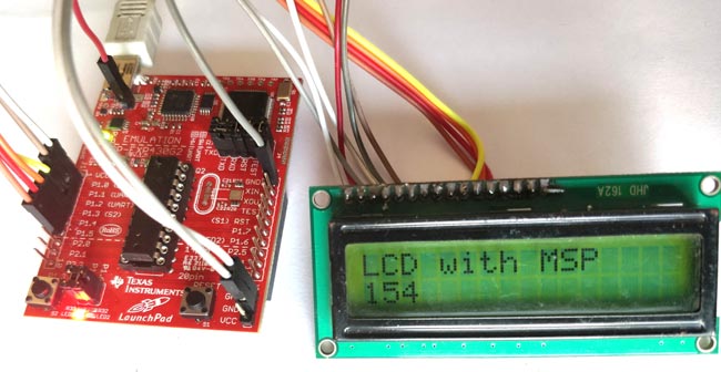
The complete working can be found in the video below. Go ahead and try changing what’s being displayed on the LCD and play with it. Hope you understood the tutorial and learned something useful form it. If you have any doubts leave them in the comment section below or use the forums. Let’s meet in another tutorial.
Complete Project Code
/*

 * Interfacing 16*2 LCD with MSP430G2553 in 4-bit mode using Energia

 */
#define RS 2

#define EN 3

#define D4 4

#define D5 5

#define D6 6

#define D7 7

#include <LiquidCrystal.h> //This librarey is insatlled by default along with IDE

LiquidCrystal lcd(RS, EN, D4, D5, D6, D7); //Let the librarey know how we have connected the LCD
void setup() {

  lcd.begin(16, 2); //We are using a 16*2 LCD display

  lcd.setCursor (0,0); //Place the cursor at 1st row 1st column

  lcd.print("MSP430G2553"); //Display a intro message

  lcd.setCursor(0, 1);   // set the cursor to 1st column 2nd row

  lcd.print("-CircuitDigest"); //Display a intro message
   delay(2000); //Wait for display to show info

   lcd.clear(); //Then clean it
}
  int test =1;

void loop() {

  lcd.print("LCD with MSP"); //Display a intro message

  lcd.setCursor(0, 1);   // set the cursor to column 0, line 1

  lcd.print(test); //Display a intro message

  delay(500);

   lcd.clear(); //Then clean it

  test++;


}

tilib: device initialization failed
can u please help with this