

This is the second tutorial of a sequence of tutorial in which we are learning the MSP430G2 LaunchPad from Texas Instruments using the Energia IDE. In the last Blinky LED tutorial we introduced our self to the LaunchPad Development Board and the Energia IDE, we also uploaded our first program which is to blink the on board LED at a regular interval.
In this tutorial we will learn how to use the Digital Read and Digital Write option to read the status of an input device like a switch, and control multiple outputs like LED’s. At the end of this tutorial you would have learnt to work with Digital Inputs and outputs, which can be used to interface many digital sensors like IR sensor, PIR sensor etc and also to turn on or off outputs like LED, Buzzer etc. Sounds interesting right!!? Let’s get started.
Material Required:
- MSP430G2 LaunchPad
- LED of any colour – 8
- Switch – 2
- 1k Resistor – 8
- Connecting wires
Circuit Diagram:
In our previous tutorial, we noticed that the launch pad itself comes with two LED and a switch on the board. But in this tutorial we are going to need more than that, as we are planning to glow eight LED lights in a sequence when a button is pressed. We will also change the sequence when another button is pressed just to make it interesting. So we have to build a circuit with 8 LED lights and two switches, the complete circuit diagram can be found below.

Here the 8 LED’s are the outputs and the two switches are the inputs. We can connect these to any I/O pin on the board but I have connected the LRD’s from pin P1.0 to P2.1 and switch 1 and 2 to pin P2.4 and P2.3 respectively as shown above.
All the cathode pins of the LED are tied to ground and the anode pin is connected to the I/O pins through a resistor. This resistor is called a Current limiting resistor, this resistor is not mandatory for a MSP430 because the maximum current it’s I/O pin can source is only 6mA and the voltage on pin is 3.6V only. However it is a good practise to use them. When any of these digital pins go high the respective LED will turn on. If you can recall the last tutorials LED program, then you will remember that digitalWrite (LED_pin_name, HIGH) will make the LED glow and digitalWrite (LED_pin_name, LOW) will turn of the LED.
The switches are the input device, one end of the switch is connected to the ground terminal and the other is connected to digital pins P2.3 and P2.4. This means that whenever we press the switch the I/O pin (2.3 or 2.4) will be grounded and will be left free if the button is not pressed. Let us see how we can use this arrangement while programming.
Programming Explanation:
The program has to be written to control the 8 LED in a sequence manner when the switch 1 is pressed and then when switch 2 is pressed the sequence has to be changed. The complete program and demonstration Video can be found at the bottom of this page. Further below I will explain the program line by line so that you can easily understand it.
As always we should start with the void setup() function inside which we would declare the pins that we are using is input or output pin. In our program the 8 LED pins are output and the 2 switches are inputs. These 8 LEDs are connected from P1.0 to P2.1 which is pin number 2 to 9 on the board. Then the switches are connected to pin P2.3 and Pin 2.4 which is pin number 11 and 12 respectively. So we have declared the following in void setup()
void setup() {
  for (int i = 2; i <= 9; i++) {
    pinMode(i, OUTPUT);
  }
  for (int i = 2; i <= 9; i++) {
    digitalWrite(i, LOW);
  }
  pinMode (11, INPUT_PULLUP);
  pinMode (12, INPUT_PULLUP);
}
As we know the pinMode() function declares the pin to be output or input and the digitalWrite() function makes it high (ON) or low (OFF). We have used a for loop to make this declaration to reduce the number for lines. The variable “i” will be incremented from 2 to 9 in the for loop and for each increment the function inside will be executed. Another thing that might confuse you is the term “INPUT_PULLUP”. A pin can be declared as input by just calling the function pinMode (Pin_name, INPUT) but here we have used an INPUT_PULLUP instead of a INPUT and they both have a noticeable change.
When we are using any microcontroller pins, the pin should either be connected to low or to high. In this case the pin 11 and 12 is connected to the switch which will be connected to ground when pressed. But when the switch is not pressed the pin is not connected to anything this condition is called a floating pin and it is bad for microcontrollers. So to avoid this we either use a pull-up or pull-down resistor to hold the pin to a state when it gets in floating. In MSP430G2553 Microcontroller the I/O pins have a pull-up resistor in-built. To use that all we have to do is call INPUT_PULLUP instead of INPUT during declaration just like w have done above.
Now lets step into the void loop() function. Whatever is written in this function will be executed for ever. The first step in our program is to check if the switch is pressed and if pressed we should start blink the LEDs in sequence. To check if the button is pressed the following line is used
if (digitalRead(12) == LOW)
Here the new function is the digitalRead() function, this function will read the status of a digital pin and will return HIGH(1) when the pin is getting some voltage and will return low LOW(0) when the pin is grounded. In our hardware, the pin will be grounded only when we press the button otherwise it will be high since we have used a pull-up resistor. So we use the if statement to check if the button was pressed.
Once the button is pressed we get into the infinite while (1) loop. This is where we start blinking the LEDs in sequence. An infinite while loop is shown below and whatever is written inside the loop will run forever until a break; statement is used.
whiel(1){
}
Inside the infinite while we check for the status of the second switch which is connected to pin 11.
If this switch is pressed we blink the LED in one particular sequence else we will blink it in another sequence.
if (digitalRead(11) == LOW)
      {
       for (int i = 2; i <= 9; i++)
        {
         digitalWrite(i, HIGH);
         delay(100);
        }
          for (int i = 2; i <= 9; i++)
             digitalWrite(i, LOW);
      }
To blink the LED in sequence we again use the for loop, but this time we use a small delay of 100 milliseconds using the delay(100) function so that we can notice the LED getting high. To make only one LED glow at a time we also use another for loop to turn off all the LED. So we turn on a led wait for some time and then turn off all the LED then increment the count turn on the LED wait for some time and the cycle continues. But all this will happen as long as the second switch is not pressed.
If the second switch is pressed then we change the sequence, the program will be more or less the same expect for the sequence of which the LED is turned on. The lines are shown below try taking a look and figuring out what has been changed.
    else
      {
        for (int i = 9; i >= 2; i--)
        {
         digitalWrite(i, HIGH);
         delay(100);
        }
                  for (int i = 2; i <= 9; i++)
             digitalWrite(i, LOW);
      }
Yes, the for loop has been altered. Previously we made the LED to glow from number 2 and all the way up to 9. But now we are going to start from number 9 and decrement all the way down to 2. This way we can notice if the switch is pressed or not.
Hardware Setup for Blinking LED Sequence:
Okay enough of all the theory and software part. Let’s, get some components and see how this program looks in action. The circuit is very simple and hence can be easily built on a breadboard. But I have soldered the LED and switches on perf board just to make it look neat. The perf board that I soldered is shown below.
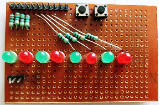
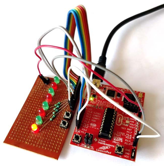
As you can see we have the output pins of the LED and switch taken out as connector pins. Now we have use the female to female connector wires to connect the LEDs and switches to out MSP430 LaunchPad board as shown in the picture below.
Uploading and Working:
Once you are done with the hardware, just connect you MSP430 board to your computer and open the Energia IDE and use the program given at the end of this page. Make sure the right board and COM port are selected in the Energia IDE and click on the Upload button. The program should get compiled successfully and once uploaded is will show “Done Uploading”.
Now press the button 1 on the board and the LED should light up in sequence as shown below
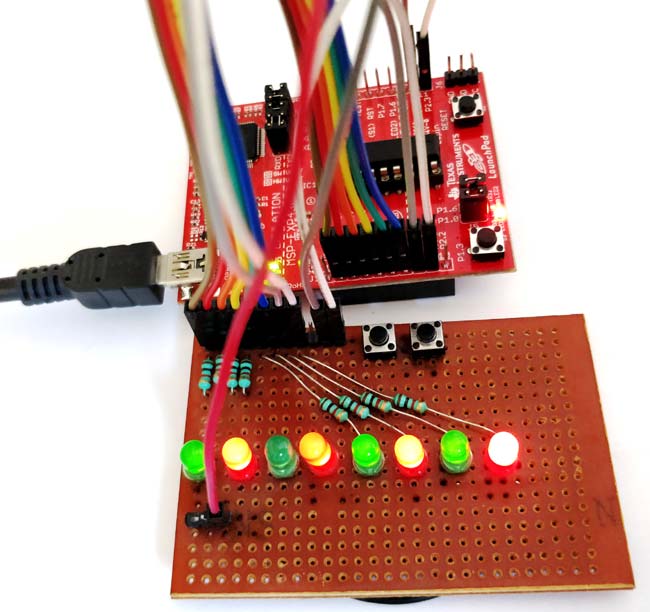
You can also hold the second button to check if the sequence is getting changed. The complete working of the project is shown in the video below. If you are satisfied with the results you can try making some changes in the code like altering the delay time changing the sequence etc. This will help you learn and understand better.
Hope you have understood the tutorial and learned something useful with it. If you had faced any problem please feel free to post the question in the comment section or use the forums. Let’s meet in another tutorial where will learn how to read analog voltages using our MSP30 launch pad.
Complete Project Code
/*
   TUTORIAL 2 - Learning to use I/O
   This program will control 8 LEDs based ont he input from two push button
   LED should be connected form P1.0 to P2.1 (pin 2 to 7)
   Switch is connected to P2.3 and P2.4 (pin 8 and 9)
*/
void setup() {
  for (int i = 2; i <= 9; i++) {
    pinMode(i, OUTPUT);
  }
  for (int i = 2; i <= 9; i++) {
    digitalWrite(i, LOW);
  }

  pinMode (11, INPUT_PULLUP);
  pinMode (12, INPUT_PULLUP);
}
// the loop routine runs over and over again forever:
void loop() {
  if (digitalRead(12) == LOW)
 {
    while (1)
    {
      if (digitalRead(11) == LOW)
      {
       for (int i = 2; i <= 9; i++)
        {
         digitalWrite(i, HIGH);
         delay(100);
        }
          for (int i = 2; i <= 9; i++)
             digitalWrite(i, LOW);
      }
      else
      {
        for (int i = 9; i >= 2; i--)
        {
         digitalWrite(i, HIGH);
         delay(100);
        }
                  for (int i = 2; i <= 9; i++)
             digitalWrite(i, LOW);
      }
    }
 }
}

Hi, good day
do you have the complet document?? becuase in this document never seew the declarations the pines