

You can find a metal detector at airports, theaters and various other public places. They are used for the safety of people to detect anyone carrying a metal (Arms etc). In this project we are going to design a simple metal detector circuit. There are so many metal detector designs but most of them are complex in design so here we are going to design a simple metal detector circuit using 555 Timer IC.
Before going further we need to understand concept of inductor and RLC circuits. Let us first talk about inductors. Inductors are nothing but coils of enameled copper wire comes in different shapes and sizes. Based on various parameters the inductance of an inductor is calculated. In all of those parameters we are basically interested in core on the inductor as depending on the core, inductance value changes drastically.
In the figure below you can see the air cored inductors, In these inductors there will be no solid core. They are basically coils left in air. The medium of flow of magnetic field generated by inductor is nothing or air. These inductors have inductances of very less value.
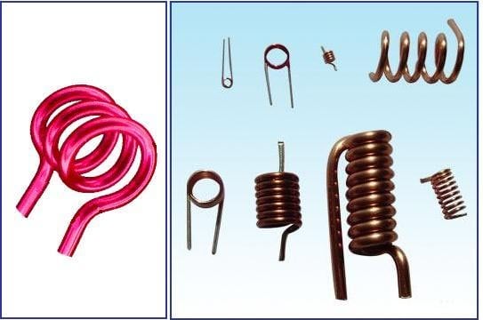
These inductors are used when the need for values of few micro Henry. For values greater than few milli these are not a suitable one. In below figure you can see a inductors of ferrite core ,
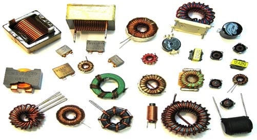
When inductor coil is wound on a core may be ferrite or an iron core, the inductance of the coil increases enormously. This value is much more than the air cored one of the same size and shape.
Now for a RLC circuit as shown in figure, the reactance or impedance between terminals “a” and “c” depends on the values of L and C if the applied signal frequency is constant.
So if the inductance value changes the value of reactance or impedance changes. How these two concepts are used together for a metal detector circuit, is explained in working section of this project.
Metal Detector Circuit Components
- +9 supply voltage
- 555 IC
- 47KΩ resistor
- 2.2µF capacitor (2 pieces)
- Speaker (8Ω)
- 170Turns of 10cm diameter coil (any gauge would work)
Metal Detector Circuit Diagram and Working

The figure shows the circuit diagram of metal detector. The 555 IC timer here acts as a square wave generator and it generate pulses with frequencies audible to human. The capacitor between pin2 and pin1 should not be changed as it is need to generate audible frequencies.
In the circuit there is an RLC circuit formed by 47K resistor, 2.2µF capacitor, and 150turn inductor. This RLC circuit is the metal detection part. Now as mentioned earlier in previous section, a metal core inductor has a high inductance value over a air cored one.
Remember the coil wound here is a air cored one, so when a metal piece is brought near the coil, the metal piece acts as a core for the air cored inductor. By this metal acting as a core, the inductance of the coil changes or increases considerably. With this sudden increase in inductance of coil the overall reactance or impedance of the RLC circuit changes by a considerable amount when compared without the metal piece.
At first when there is no metal piece the signal fed to speaker causes some audible sound. Now with the reactance change around the RLC circuit the signal sent to speaker will no longer be the same as before, because of this the sound produced by the speaker will be of different to the first one.
So whenever a metal is brought near the coil, the impedance of RLC changes making the signal to change resulting in variation to sound generated in speaker. You can also check this Arduino based metal detector.
Common Tips:
- Enamel should be removed at the tips of coil for soldering connections.
- With different gauge we will have different RLC impedance, so one should experiment with resistance in RLC circuit for sensitive metal detection.
- The speaker can be of any type. But with resistance less than 8Ω, the timer might get heated.
- Use supply voltage higher than 5V.
Comments
Its not 2.2mf, its 2.2uF. Its micro (u) not milli (m). And yes the value shouldn't be changed.
RL/C will become different.
Nice
i need this circuit
The circuit is present in the description.
i neded circuit board the detector and
the real value of capacitors 2,2 mf o 2,2 nano? thanks very
It really works because i have made this circui & it works perfectly.
What to do to increase it's sencitivity so that it can be used in various industries?
Can I change the speaker to motor or solenoid?
It's nice but the speaker turns always on.
It will be fine if the speaker turns off when there are no metal near inductor (coil)
and the speaker Turns on when a metal brought near inductor .
how can I do that?
can you tell me the reason and explain the jop of every component of the circuit please ??
How to increase its range ?
Can u help me out with design Steps? How to choose the values of R, L, C and inductance?
I now understand the concept behind metal detectors.
Thank you.
i want to make door frame metal detector. Can anyone help me?
its works better on alominom
its awsooome to make
i need help to design turn off speaker when they is no metal found.. please help me to design..
plz lets us know about theoritical design about this project
29 gauge wire is work or not
I didn't connect this circuit, although I have question: does the voltage across the buzzer changes if a metal is brought near the coil?
Output Frequency of 555 changes, when we bring Metal near to the coil, so sound of Speaker changes according to the frequency.
i have 2 cd player and 1 9volt battery and headphone...can you help me make a metal detector
What transformer should be used so that it connects directly in the power source?
You can try having 9v or 5v of regulated DC power supply form the 9-0-9 1A transformer
nice mister anyway can u give us the video of how it works
thanks
can i use the coil of 5 cm diameter
No of Turns and diameter are important in the coil, so use it as suggested in the article.
please can you explain to what causes the continous noise or sound in the speaker.. need the answer as this a likely question in my project defense
i need detail about this project
what is the Detecting distance ?
and if i want to increase it , what I can do.
the speaker doesnt make any sound what wud be the problem pls help urgent
is it 150 turns or 170? wat xactly?
made circuit using 2.2uf50v 10uf50v capacitors 47k resistor ne555 ic 8ohm speaker on coil i used 0.1mm enameled wire 150turns of120mm diameter . the detactor produces a high pitch sound which does not change even when coil is swept over a metal object. pliz help with specific voltages of capacitors and specific resistance of search coil
I WANT TO MAKE METAL DETECTOR WHICH DETECT METAL FOR 10 FEET DOWN THE EARTH PLZ HELP ME
Thanks
What is the function of 10 micro farad capacitor here...??
I m doing this project in my collage
the 555 timer either sourcing or sinking a fixed amount of current from its pin 3,
so I see as the output is a fixed squarawave tone so the increasing of L coil will increase voltage on it that increasing current draining from pin 3 hence reducing tone....very simple ! I will build the circuit and examine it under oscilloscope and if there is time I will publish results here ...god willing...
Yes @hossameddeen, please share the results of you findings when you are done :)
I used all the above components but the circuit is not working.
can it detect all types of metal or only iron metal?? plz tell...
Why there is a continuous sound occuring.can i know the reason
Because 555 timer is generating a square wave which is causing the sound and bringing metal near to it will change the frequency of that square wave hence the sound will also change.
How can we find the frequency generated by IC in this circuit? Please inform me because I'm in great need of it.
Can anyone tell me how much does each components cost?
Whats are the voltage of capacitor
I can't find inductance in my country
My country stops import it
What should I do?
I am a hobbyist of metal detecting.
Can this metal detector circuit detect all kinds of metal?
There might be large functional difference.
Hallo friend i like to learn this metal please send me all project until final thanks
Could we replace the speaker with and LED instead?
C
an we just use the normal copper wire..?
in this circuit diagram pin 2 and pin 6 are connected.I think its only astable multivibrator. am i right sir ??can we design a metal detector using monostable multivibrator configuration where pin 6and pin7 are connected???
What is the use of the 10 micro farad capacitor?
what is the purpose of the 10uF capacitor in the circuit
Its a smoothing capacitor to filter noise. It is optional and hence you can ignore it if you cannot find a 10u cap
Thank you....bro
it has done
I made the exact same circuit. The coil of 170 turns, 22 gauge copper wire, 10 cm diameter and all the other components were kept the same as mentioned, but it did not work. I've tried it multiple times but not even the slightest of change in noise occurs.
Help me out. What could be the probable mistake?
Hey, did you figure out the same mistake because the same issue i'm also having.
Even i couldn't get the output.
I have coil of 500 turns remaining all specs are same.
How thick should be the copper wire
I want advantages of this project
Thanks for sharing this project. I was able to make a working copy with the specified components. I'm wondering if it would be possible to filter out the constant tone when no metal is near the coil by simply adding a basic RLC band stop filter between the output and the speaker. It would probably need to be a sufficiently high order one to retain the sensitivity, and band stop because both higher and lower frequencies should be able to pass (to detect both ferromagnetic e.g. iron and non-ferromagnetic e.g. aluminium). Please comment if you have tried something like this :) Also would be interested if someone had experimented with differently shaped coils (for example '8'-shaped) to improve the detection range.

can weuse 10 mf capacitor instead of 2.2 mf capacitor