In this DIY tutorial, we are going to build an IoT-based GPS Location tracker using NEO-6M GPS Module. This Location Tracker Board consists of a NodeMCU, OLED Display Module, NEO-6M GPS Module, and 3.7 to 6V booster circuit. Here, we have also created a simple local webserver to display the location details. This webserver contains a link to directly check the location in Google Maps.
We have used PCBWay to provide the PCB boards for this project. In the following sections of the article, we have covered in detail the complete procedure to design, order, and assemble the PCB boards for the IoT-based Location Tracker Board. Previously, we have also built Lora Based GPS Tracker and Vehicle Tracking and Accident Alert System.
Components Required for GPS Location Tracker
- NodeMCU ESP8266
- NEO-6M GPS Module
- OLED Display Module
- FP6291 Boost Converter IC
- 3× Resistor (10k, 100k, 48k)
- 6× Capacitor (2×0.1µf, 1×10µf, 2×20µf)
- 1× Inductor (4.7µH)
- 1× Diode (1N5388BRLG)
- 18650 Lithium Cell
- 18650 Cell Holder
- 6-Pin Push Button Switch
IoT Based Location Tracker Circuit Diagram
The complete circuit diagram for NodeMCU GPS Tracker Board is shown below. The schematic was drawn using EasyEDA. This HAT consists of a NodeMCU with NEO-6M GPS Module, OLED Display Module, and Booster circuit. The booster circuit is designed around a dedicated FP6291 Boost Converter IC to boost the battery voltage from 3.7v to 6V. This location tracking board can be used to track Cars/Bikes/almost anything.
![]()
FP6291 IC is a 1 MHz DC-DC Step-Up Booster IC, mainly used in the application, for example, getting stable 5V from 3V battery. You only need few extra components to design a booster circuit with this IC. Here, in this circuit, the Boost Converter circuit gets the input supply through battery terminals (+ and -). This input voltage is then processed by FP6291 IC to give a stable 6V DC supply to the VIN pin of NodeMCU.
The output voltage from this IC can be configured using the potential divider circuit. The formula to calculate the output voltage is:
VOUT = 0.6(1+ R1/ R2)
Fabricating PCB for NodeMCU GPS Tracker Board
Now that we understand how the schematics works, we can proceed with building the PCB for our project. You can design the PCB using any PCB software of your choice. We have used EasyEDA to fabricate PCB for this project. We have previously used EasyEDA many times and found it very convenient to use compared to other PCB fabricators. Click on the link to check all the PCB projects. They also offer a component sourcing service where they have a large stock of electronic components, and users can order their required components along with the PCB order.
While designing the circuits and PCBs, you can also make your circuit, and PCB designs public so that other users can copy or edit them and can take benefit from your work. We have also made this NodeMCU GPS Tracker PCB design file and GERBER file public, check the link given below:
![]()
Now, that our Design is ready, it is time to get them fabricated using the Gerber file. To get the PCB done is quite easy; simply follow the steps given below.
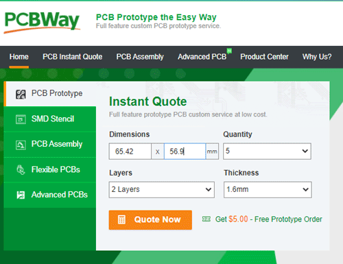
Step 1: Go to https://www.pcbway.com/, sign up if this is your first time. Then, in the PCB Prototype tab, enter the dimensions of your PCB, the number of layers, and the number of PCB you require.
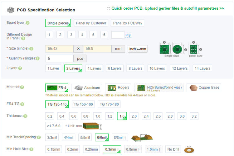
Step 2: Proceed by clicking on the ‘Quote Now’ button. You will be taken to a page where to set a few additional parameters if required like the material used track spacing, etc. but usually, the default values work fine.
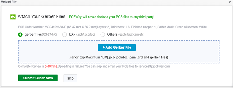
Step 3: The final step is to upload the Gerber file and proceed with the payment. To make sure the process is smooth, PCBWAY verifies if your Gerber file is valid before proceeding with the payment. This way, you can be sure that your PCB is fabrication-friendly and will reach you as committed.
Assembling the NodeMCU Location Tracker PCB
After a few days, we received our PCB in a neat package and the PCB quality was good as always. The top layer and the bottom layer of the board are shown below.
![]()
After making sure that the tracks and footprints were correct, I proceeded with assembling the PCB. The completely soldered board looked like as shown in the image below:
![]()
![]()
Programming NodeMCU for Getting GPS Data
The complete program can be found at the end of the page, the explanation of the same is as follows. Make sure you have installed the libraries for the GPS module and OLED display before proceeding with the code.
Like always, we begin the program by adding the required libraries. Here, the Adafruit_SSD1306.h library is used for OLED display, and the TinyGPS++ and SoftwareSerial library is used for GPS communication.
#include <TinyGPS++.h>
#include <SoftwareSerial.h>
#include <ESP8266WiFi.h>
#include <Wire.h>
#include <Adafruit_GFX.h>
#include <Adafruit_SSD1306.h>
Then, define the OLED width and height. In this project, we’re using a 128×64 SPI OLED display. You can change the SCREEN_WIDTH and SCREEN_HEIGHT variables according to your display.
#define SCREEN_WIDTH 128
#define SCREEN_HEIGHT 64
Then, create an Adafruit display instance with the width and height defined earlier with the I2C communication protocol.
Adafruit_SSD1306 display(SCREEN_WIDTH, SCREEN_HEIGHT, &Wire, -1);
Inside the setup() function, begin the serial monitor and also initialize the software serial as “ss” for communication with the GPS module and the OLED display with the begin() function.
void setup()
{
  Serial.begin(115200);
  ss.begin(9600);
  WiFi.begin(ssid, password);
  while (WiFi.status() != WL_CONNECTED)
  {
    delay(500);
     }
    if(!display.begin(SSD1306_SWITCHCAPVCC, 0x3C)) { // Address 0x3D for 128x64
    Serial.println(F("SSD1306 allocation failed"));
  }
}
Now, inside the loop() function, we will use the TinyGPS library to extract the latitude, longitude, date, and time data from the string and stored the values in the variables “lat_str”, “lng_str, “date_str” and “time_str” respectively. TinyGPS library has an inbuilt function to get the required data from the NMEA string. The code for the same is as follows:
if (gps.encode(ss.read()))
    {
      if (gps.location.isValid())
      {
        latitude = gps.location.lat();
        lat_str = String(latitude , 6);
        longitude = gps.location.lng();
        lng_str = String(longitude , 6);
}
      if (gps.date.isValid())
      {
                date_str = "";
        date = gps.date.day();
        month = gps.date.month();
        year = gps.date.year();
        if (date < 10)
          date_str = '0';
        date_str += String(date);
        date_str += " / ";
………………………………………..
………………………………………..
Once a client is connected, the webserver needs to send the response to the client. Here, all the HTML code is embedded into a variable called “s”. Then this variable is printed using the client.print(s) to send all embedded HTML code to the webpage. The latitude, longitude, date, and time values are updated once the data is received from the GPS module.
String s = "HTTP/1.1 200 OK\r\nContent-Type: text/html\r\n\r\n <!DOCTYPE html> <html> <head> <title>Location Tracking with NodeMCU</title> <style>";
  s += "a:link {background-color: YELLOW;text-decoration: none;}";
  s += "table, th, td {border: 1px solid black;} </style> </head> <body> <h1  style=";
  s += "font-size:300%;";
  s += " ALIGN=CENTER> Locatoin Tracking with NodeMCU</h1>";
  s += "<p ALIGN=CENTER font-size:150%;""";
  s += "> <b>Location Details</b></p> <table ALIGN=CENTER style=";
  s += "width:50%";
  s += "> <tr> <th>Latitude</th>";
  s += "<td ALIGN=CENTER >";
  s += lat_str;
…………………………………..
…………………………………..

NodeMCU GPS Tracker Working
![]()
Once the hardware and program are ready, upload the code to the NodeMCU Board and power the setup. If the LED on the GPS module is blinking (It may take a couple of minutes), this means that the module is looking for a satellite connection to get co-ordinates, if not take the GPS module to the open area. In the serial monitor, you will be able to see the local IP address of your NodeMCU. Now, navigate to the browser and type in the NodeMCU IP address and press ENTER. You will be able to see the Location, Date, and Time displayed as below:
![]()
When you click on “Click here”, it will open the location in Google Maps like below:
![]()
The complete working can also be found in the video given at the bottom of this page. Hope you understood the tutorial and enjoyed building something useful with it. If you have any doubts, you can leave them in the comment section below.
Complete Project Code
#include <TinyGPS++.h>

#include <SoftwareSerial.h>

#include <ESP8266WiFi.h>

#include <Wire.h>

#include <Adafruit_GFX.h>

#include <Adafruit_SSD1306.h>

#define SCREEN_WIDTH 128 // OLED display width, in pixels

#define SCREEN_HEIGHT 64 // OLED display height, in pixels

// Declaration for an SSD1306 display connected to I2C (SDA, SCL pins)

Adafruit_SSD1306 display(SCREEN_WIDTH, SCREEN_HEIGHT, &Wire, -1);

TinyGPSPlus gps;  // The TinyGPS++ object

SoftwareSerial ss(2, 0); // The serial connection to the GPS device

const char* ssid = "Galaxy-M20";

const char* password = "ac312124";

float latitude , longitude;

int year , month , date, hour , minute , second;

String date_str , time_str , lat_str , lng_str;

int pm;

//int numreadings = 10;

String latarray[20];

String lngarray[20];

//String current_latarray[10], current_lngarray[10], previous_latarray[10], previous_lngarray[10] ;

unsigned int i = 0;

const unsigned long Interval = 13000;

unsigned long previousTime = 0;

WiFiServer server(80);

void setup()

{

  Serial.begin(115200);

  ss.begin(9600);

  delay(2000); // Pause for 2 seconds

  Serial.println();

  Serial.print("Connecting to ");

  Serial.println(ssid);

  WiFi.begin(ssid, password);

  while (WiFi.status() != WL_CONNECTED)

  {

    delay(500);

    Serial.print(".");

  }

  Serial.println("");

  Serial.println("WiFi connected");

  server.begin();

  Serial.println("Server started");

  // Print the IP address

  Serial.println(WiFi.localIP());

  if(!display.begin(SSD1306_SWITCHCAPVCC, 0x3C)) { // Address 0x3D for 128x64

    Serial.println(F("SSD1306 allocation failed"));

    for(;;);

  }

}

void loop()

{

  unsigned long currentTime = millis();

  display.clearDisplay();

  display.setTextSize(1);

  display.setTextColor(WHITE);

  while (ss.available() > 0)

    if (gps.encode(ss.read()))

    {

     if (currentTime - previousTime >= Interval) {

      if (gps.location.isValid())

      {

        //Serial.print("Getting Data");

        latitude = gps.location.lat();

        lat_str = String(latitude , 6);

        longitude = gps.location.lng();

        lng_str = String(longitude , 6);

        latarray[i] = lat_str;

        lngarray[i]= lng_str;

        i++;

        Serial.print(i);

        if (i>=20)

       // {

          i=0; //reset to beginning of array, so you don't try to save readings outside of the bounds of the array

        // }

        Serial.println("Latitude:");

        Serial.println(latarray[i]);

        Serial.println("Longitude:");

        Serial.println(lngarray[i]);

        Serial.println();

        display.setCursor(0, 20);

        display.println("Lat:");

        display.setCursor(27, 20);

        display.println(lat_str);

        display.setCursor(0, 40);

        display.println("Lng:");

        display.setCursor(27, 40);

        display.println(lng_str);

        display.display();

        }

        previousTime = currentTime;

       }

      //}

      if (gps.date.isValid())

      {

        //Serial.print("Getting Time");

        date_str = "";

        date = gps.date.day();

        month = gps.date.month();

        year = gps.date.year();

        if (date < 10)

          date_str = '0';

        date_str += String(date);

        date_str += " / ";

        if (month < 10)

          date_str += '0';

        date_str += String(month);

        date_str += " / ";

        if (year < 10)

          date_str += '0';

        date_str += String(year);

      }

      if (gps.time.isValid())

      {

        time_str = "";

        hour = gps.time.hour();

        minute = gps.time.minute();

        second = gps.time.second();

        minute = (minute + 30);

        if (minute > 59)

        {

          minute = minute - 60;

          hour = hour + 1;

        }

        hour = (hour + 5) ;

        if (hour > 23)

          hour = hour - 24;

        if (hour >= 12)

          pm = 1;

        else

          pm = 0;

        hour = hour % 12;

        if (hour < 10)

          time_str = '0';

        time_str += String(hour);

        time_str += " : ";

        if (minute < 10)

          time_str += '0';

        time_str += String(minute);

        time_str += " : ";

        if (second < 10)

          time_str += '0';

        time_str += String(second);

        if (pm == 1)

          time_str += " PM ";

        else

          time_str += " AM ";

      }

    }

  // Check if a client has connected

  WiFiClient client = server.available();

  if (!client)

  {

    return;

  }

  // Prepare the response

  String s = "HTTP/1.1 200 OK\r\nContent-Type: text/html\r\n\r\n <!DOCTYPE html> <html> <head> <title>Location Tracking with NodeMCU</title> <style>";

  s += "a:link {background-color: YELLOW;text-decoration: none;}";

  s += "table, th, td {border: 1px solid black;} </style> </head> <body> <h1  style=";

  s += "font-size:300%;";

  s += " ALIGN=CENTER> Locatoin Tracking with NodeMCU</h1>";

  s += "<p ALIGN=CENTER style=""font-size:150%;""";

  s += "> <b>Location Details</b></p> <table ALIGN=CENTER style=";

  s += "width:50%";

  s += "> <tr> <th>Latitude</th>";

  s += "<td ALIGN=CENTER >";

  s += lat_str;

  s += "</td> </tr> <tr> <th>Longitude</th> <td ALIGN=CENTER >";

  s += lng_str;

  s += "</td> </tr> <tr>  <th>Date</th> <td ALIGN=CENTER >";

  s += date_str;

  s += "</td></tr> <tr> <th>Time</th> <td ALIGN=CENTER >";

  s += time_str;

  s += "</td>  </tr> </table> ";

   if (gps.location.isValid())

  {

    // s += "<p align=center><a style=""color:RED;font-size:125%;"" href=""http://maps.google.com/maps?&z=15&mrt=yp&t=k&q=";

     s += "<p align=center><a style=""color:RED;font-size:125%;"" href=""https://www.google.com/maps/dir/";

 //https://www.google.com/maps/dir/26.8172985,75.8286322/26.8181889,75.830…;

    for (int j=0; j<20; j++)

    {

    s += latarray[j];

    s += ",";

    s += lngarray[j];

    if (j<10)

    s += "/";

    }

    s += """ target=""_top"">Click here!</a> To check the location in Google maps.</p>";

  }

  s += "</body> </html> \n";

  client.print(s);

  delay(200);

 }
Comments
Great project! But how do you
Great project! But how do you pass long. and lat. to google maps with no internet connection??

Add a SIM module to report location via SMS?