

“Good morning. It’s 7 A.M. The weather in Malibu is 72 degrees…” these were the first words of JARVIS when being introduced in the Marvel Cinematics Universe. Most Iron Man fans should be able to recollect this scene and remember that JARVIS was able to open a window (kind-of) in the morning and give updates on time and weather. In the movie, the window Glasses were actually made of See-Through Touch Displays and hence JARVIS was able to make it turn from black to transparent and also display weather stats on it. But, in reality, we are far away from See-through touch screens, and the closer we can get is to control window blinds or constraints automatically.
So, in this project, we are going to build exactly that, we will build an automated motorized blind that would open and close automatically at pre-defined times. Previously, we have built many home automation projects in which we automated the lights, motors, etc. You can check them out if you are interested. So, coming back, these Arduino controlled blinds can also take commands from Google assistant so that you can open or close your window blinds remotely through voice commands. Intriguing? Then, let's get it built.
Components Required to Build Arduino Automated Blinds
The project is relatively simple and there are not many components required. Just gather the items listed below.
- NodeMCU
- Stepper Motor – 28BYJ-48
- Stepper Motor Driver Module
- LM117-3.3V
- Capacitors (10uf,1uf)
- 12V DC Adapter
- Perf Board
- Soldering kit
- 3D Printer
Controlling Roller Blinds using Arduino
Now there are many types of Blinds in the market, but the most commonly used one has a rope with beadings (as shown below) that can be pulled to open or close the blinds.
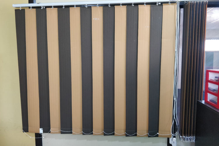
When we pull this circular rope in a clockwise direction, the window blinds will open and when we pull this rope in an anti-clockwise direction, the window blinds will close. So, if we were to automate this process, all we have to do is use a motor to pull this rope in a clockwise or anti-clockwise direction and we will be done with it. In fact, this is what we are going to do in this project; we will be using the 28BYJ-48 stepper motor along with a NodeMCU to pull the beaded rope.
Design and Build the Window Blind Gear
The Electronics part of this project was fairly simple and straight forward, the challenging part was in building the Blind Gear that could pull the beaded rope. So let’s start this article with the blind gear design, I am not going to get into details on how to design the gear, but this basic idea should help you out. An image of the rope with the beads on it is shown below.

Again, there are many types of ropes but the most commonly used ropes are the center-to-center distance of each beading is 6mm and the diameter of each beading is 4mm. Using this information, we can start the design of our gear. If the rope on your blinds has the same dimensions as discussed, you can simply skip this step and download the STL file provided in this article and print the gear. If your rope has a different beading arrangement, then this is how you should re-design the blind gear.
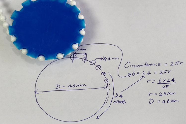
I decided to have 24 beads on my gear to get an optimum gear wheel size, you can select any number close to this for your gear wheel to be large or small. So now, we know that the distance between each beading is 6mm and we need 24 beads on our gear. Multiplying both will give the circumference of the gear wheel. With this data, you can calculate the radius of the gear wheel. As you can see in the above image, the diameter of my gear wheel was calculated to be around 46 mm. But remember, this is not the actual diameter of the gear because we have not accounted for the diameter of the beading which is 4mm. So, the actual diameter of the gearwheel will be 42 mm, I printed and tested many gear wheels before I found the one that works the best. If you are not into designs, just download and print the STL files from the next paragraph and continue with your project.

3D Printing the Motor Holder and Blind Gear
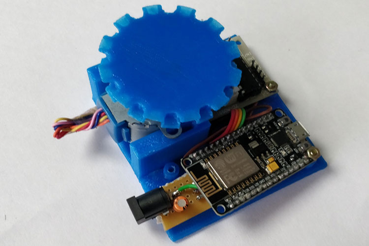
Along with the gear, we will also need a small casing that can be drilled onto the wall and hold the stepper motor in position, both the casing and the gear used in this project are shown below.
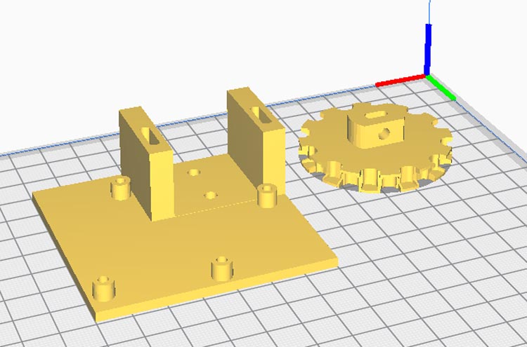
You can find complete design files and STL files on the Arduino Blind Control Thingiverse page given below. You can just download and print your blind gear and motor case.
Download STL files for Blind Gear and Motor Case
Circuit Diagram for Arduino Blinds Control
Once you are ready with the gear and assembly, it is easy to proceed with the electronics and software part. The complete circuit diagram for the IoT Blind control project is shown below.

We have used a 12V adapter to power the entire setup; the LM1117-3.3V regulator converts the 12V to 3.3V which can be used to power the NodeMCU board. The stepper motor driver module is directly powered from the 12V adapter. I did try running the stepper motor on 5V, but then it did not provide enough torque to pull the blinds, so make sure you are also using 12V.
Apart from that, the circuit is pretty simple, if you are new to stepper motors, do look into the basics of stepper motor article to understand how it works and how it can be used with a microcontroller.

Blynk Application for Arduino Blind Control
Before we get into the Arduino program for Controlling Blinds, lets open the blynk application and create some buttons using which we can open or close our blinds. We will also need this later to control from Google home.
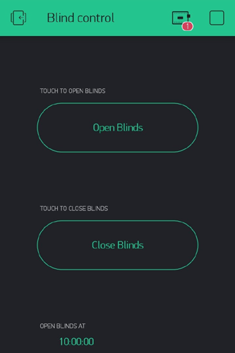
I have just added two buttons to open and close the blinds and one-timer to open the blinds at 10:00 am every day. You can add multiple timers to open or close the blinds at different intervals of the day. Basically, when we have to close the blinds, we have to trigger virtual pin V1 and when we have to open the blinds, we have to trigger virtual pin V2. The program to control the stepper motor based on the button pressed here will be written on the Arduino IDE, the same is discussed below.
Programming NodeMCU to Control Blinds using Blynk
The complete ESP8266 code for this Blind Control Project can be found at the bottom of this page. Our program has to wait for a command from the blynk application and based on that command, we have to rotate the stepper motor either in a clockwise direction or in an anti-clockwise direction. The important segments of the code are discussed below.
According to our circuit diagram, we have used digital pins 1, 2, 3, and 4 on nodemcu to control our stepper motor. So, we have to create an instance called stepper using these pins as shown below. Notice that we have defined the pins in order 1, 3, 2, and 4. It was done deliberately and is not a mistake; we have to swap pins 2 and 3 for the motor to work properly.
// create an instance of the stepper class using the steps and pins
Stepper stepper (STEPS, D1, D3, D2, D4);
In the next step, we have to share our blynk application authentication token and the Wi-Fi credentials to which our IoT Blind controller has to be connected. If you are not sure how to get this Blynk auth token, refer to the Blynk LED Control project to understand the basics of the blynk application and how to use it.
// You should get Auth Token in the Blynk App.
// Go to the Project Settings (nut icon).
char auth[] = "l_b47mF1hioCc_7FzdKMJJeFnJjTxxxx";
// Your WiFi credentials.
// Set password to "" for open networks.
char ssid[] = "CircuitDigest";
char pass[] = "dummy123";
Moving on with our code, after the setup function, we have defined two methods for blynk. As mentioned previously, we have to define what virtual pins V1 and V2 should do. The code for the same is given below.
BLYNK_WRITE (V1) //CLOSE the BLINDS
  {
    Serial.println("Closing Blinds");
    if (opened == true)
    {
    for (int c_val = 0; c_val <= 130; c_val++) //rotate in Counter-Clockwise for closing
    {
      stepper.step(c_val);
      yield();
    }
    closed = true;
    opened = false;
    disable_motor(); // always desable stepper motors after use to reduce power consumption and heating
    }
  }
  BLYNK_WRITE(V2) // OPEN the BLINDS
  {
    Serial.println("Opening Blinds");
    if (closed == true)
    {
    for (int cc_val = 0; cc_val >= -130; cc_val--) //rotate in Clockwise for opening
    {
      stepper.step(cc_val);
      yield();
    }
    opened = true;
    closed = false;
    }
    disable_motor(); // always desable stepper motors after use to reduce power consumption and heating
  }
As you can see V1 is used to close the blinds and the V2 is used to open the blinds. A for loop is used to rotate the motors in a clockwise or anti-clockwise direction for 130 steps. I experimented with my blinds to find that with 130 steps, I am able to fully open and close my blinds. Your number might vary. The for loop to rotate stepper motor in a clockwise and counter-clockwise direction is shown below.
for (int c_val = 0; c_val <= 130; c_val++) //rotate in Counter-Clockwise for closing
    {
      stepper.step(c_val);
      yield();
    }
  for (int cc_val = 0; cc_val >= -130; cc_val--) //rotate in Clockwise for opening
    {
      stepper.step(cc_val);
      yield();
    }
You can also notice two Boolean variables “opened” and “closed” in our program. These two variables are used to prevent the motor from opening or closing the blinds twice. Meaning, the blinds will open only when it is previously closed and it will close only when it is previously opened.
How to increase the speed of the 28BJY-48 Stepper motor?
One drawback of using the 28BJY-48 stepper motor is that it is very slow. These motors were originally manufactured to be used in high-precision low-speed applications, so do not expect these motors to rotate at high speed. If you want to increase the speed of the stepper motor using Arduino, there are two parameters that you can change. One is the #define STEPS 64, I found that when steps are defined as 64, the motor was comparatively faster. Another parameter is a stepper.setSpeed(500); again I found 500 to be an optimal value, anything more than that actually makes the stepper motor slower.
Do you know any other way to increase the speed of these motors? If yes, leave them in the comment section below.
How to prevent the stepper motor from overheating?
Stepper motors should always be disabled when not in use to prevent overheating. Disabling a stepper motor is very simple; just change the pin status of all the four GPIO pins that are controlling the stepper motor to low. This is very important, else your motor might get very hot at +12V and damage itself permanently. The program to disable the stepper motor is given below.
void disable_motor() //turn off the motor when done to avoid heating
{
  digitalWrite(D1,LOW);
  digitalWrite(D2,LOW);
  digitalWrite(D3,LOW);
  digitalWrite(D4,LOW);
}
Controlling Window Blinds using Google Assistant
We are going to use the blynk API to control the blinds via Google assistant, it will be similar to our Voice Controlled Home automation project, so do check that if interested. Basically, we have to trigger the below link when we say a pre-defined phrase to Google Assistant.
//http://188.166.206.43/l_b47mF1hioCc_7FzdKMJJeFnJjTxxxx/update/V1?value=1 /
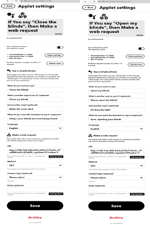
Make sure you change the authentication token to the one provided by your blynk application. You can even test this link on your chrome browser to see if it is working as expected. Now that the link is ready, we simply have to get over to IFTTT and create two applets that can trigger virtual pin V1 and V2 when we ask to close and open the blinds. Again, I am not getting into the details of this because we have done this many times. If you need more help, refer to this Voice controlled FM radio project, just replace the adafruit services with webhooks. I am also sharing a screenshot of my snippet for reference.
Arduino based Automatic Window Blind Control – Demonstration
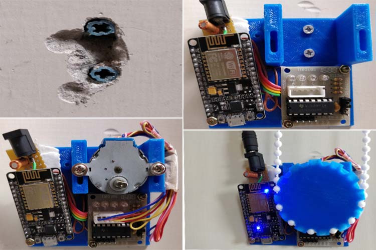
After the circuit and 3D printed enclosures are ready, just assemble the device on the wall by drilling two holes on the wall. My mounting setup is shown in the pictures below.
After that, make sure your blinds are in an open condition and then power on the circuit. Now, you can try to close the blinds from the blynk application or through Google Assistant and it should work. You can also set timers on the blynk application to automatically open and close the blind at a particular time of the day.
The complete working of the project can be found in the video given below; if you have any questions, feel free to write them in the comment section below. Also, you can use our forums for other technical discussions.
Complete Project Code
// Arduino Program to control blinds usig stepper motor

#include <ESP8266WiFi.h>

#include <BlynkSimpleEsp8266.h>

#include <Stepper.h> // Include the header file

#define BLYNK_PRINT Serial

// change this to the number of steps on your motor

#define STEPS 64

// create an instance of the stepper class using the steps and pins

Stepper stepper(STEPS, D1, D3, D2, D4);

// You should get Auth Token in the Blynk App.

// Go to the Project Settings (nut icon).

char auth[] = "l_b47mF1hioCc_7FzdKMJJeFnJjTxxxx";

// Your WiFi credentials.

// Set password to "" for open networks.

char ssid[] = "CircuitDigest";

char pass[] = "dummy123";

//Run the program only after opening the blinds

boolean closed = false;

boolean opened = true;

void disable_motor() //turn off the motor when done to avoid heating

{

  digitalWrite(D1,LOW);

  digitalWrite(D2,LOW);

  digitalWrite(D3,LOW);

  digitalWrite(D4,LOW);

}

void setup()

{

  pinMode(D0, OUTPUT); //on-board LED as output

  digitalWrite(D0,HIGH); //turn this light on

  Serial.begin(9600);

  stepper.setSpeed(500);

  Blynk.begin(auth, ssid, pass);

  //http://188.166.206.43/l_b47mF1hioCc_7FzdKMJJeFnJjxxxx_/update/V1?value=1 /

  digitalWrite(D0,LOW); //turn it off after connecting to blynk

}

BLYNK_WRITE(V1) //CLOSE the BLINDS

  {

    Serial.println("Closing Blinds");

    if (opened == true)

    {

    for (int c_val = 0; c_val <= 130; c_val++) //rotate in Counter-Clockwise for closing

    {

      stepper.step(c_val);

      yield();

    }

    closed = true;

    opened = false;

    disable_motor(); // always desable stepper motors after use to reduce power consumption and heating

    }

  }

  BLYNK_WRITE(V2) // OPEN the BLINDS

  {

    Serial.println("Opening Blinds");

    if (closed == true)

    {

    for (int cc_val = 0; cc_val >= -130; cc_val--) //rotate in Clockwise for opening

    {

      stepper.step(cc_val);

      yield();

    }

    opened = true;

    closed = false;

    }

    disable_motor(); // always desable stepper motors after use to reduce power consumption and heating

  }

void loop()

{

  Blynk.run();

}
Comments
how much budget is needed for this project?

This program can also serve other purposes. Thank you Aswinth Raj