

How cool it be to turn on the lights automatically as soon as you enter in your home and turn it off again when you leave! Yes, a simple application can do this for you. Here in this project, we will use ESP32 as BLE client and fitness band as BLE server, so whenever a person wearing the fitness band comes in the range of ESP32 Bluetooth, the ESP32 detects it and turn on the Light. Any Bluetooth devices which have BLE server capabilities can be used as a trigger device to control any home appliance using ESP32.
We have already explored the BLE (Bluetooth Low Energy) functionalities of the ESP32 module and I am quite thrilled by it. To give a recap, this module has both classic Bluetooth and Bluetooth Low Energy (BLE), the classic Bluetooth can be used to transfer songs or files and the BLE option can be used for battery optimized applications like Bluetooth beacons, fitness bands, proximity advertisements, etc. It is also possible to use it as a serial Bluetooth like the HC-05 or HC-06 modules for simple microcontroller projects.
As you know the ESP32 BLE can operate in two different modes. One is the server mode which we have already discussed by utilizing the GATT service to mimic a battery level indicator service. In that exercise, the ESP32 acted as a server and our mobile phone acted as a client. Now, let us operate the ESP32 as a client and try connecting it to other BLE servers like my fitness band.
All BLE servers including my fitness band are in constant advertising mode that is they can always be discovered when scanned by a client. By leveraging this feature we can use these fitness bands as a proximity switch, meaning these fitness bands are always tied to the user’s hand and by scanning for the band we can detect if the person is within range. This is exactly what we are going to do in this article. We will program the ESP32 to act as a BLE client and constantly keep scanning for BLE devices; if we find the fitness band in range we will try connecting to it and if the connection is successful we can trigger a light bulb by toggling one of the GPIO pins on the ESP32. The method is reliable because each BLE server (fitness band) will have a unique hardware ID so no two BLE server devices will be identical. Interesting right?!!! Now, let’s get building
Pre-requisites
In this article, I assume that you are already familiar on how to use the ESP32 board with Arduino IDE, if not fall back to getting started with ESP32 tutorial.
We have divided the complete ESP32 Bluetooth into three segments for ease of understanding. So it is recommended to go through the first two tutorials before starting with this one.
- Serial Bluetooth on ESP32 toggling LED from Mobile Phone
- BLE server to send Battery level data to Mobile Phone using GATT Service
- BLE client to scan for BLE devices and act as a beacon.
We have already covered the first two tutorials, here we are proceeding with the last one to explain ESP32 as BLE client.
Materials Required
- ESP32 Development Board
- AC Load (Lamp)
- Relay Module
Hardware
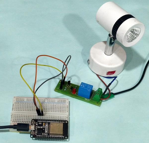
The hardware for this ESP32 BLE Client project is pretty plain since most of the magic happens inside the code. The ESP32 has to toggle an AC lamp (Load) when the Bluetooth signal is discovered or lost. To toggle this load we will use a Relay, and since the GPIO pins of ESP32 are only 3.3V compatible we need a Relay module that can be driven with 3.3V. Just check what transistor is used in the Relay module if it is BC548 you are good to go else build your own circuit by following the circuit diagram below.

Warning: The circuit deals with direct 220V AC mains voltage. Be careful with live wires and make sure you don’t create a short circuit. You have been warned.
The reason behind using BC548 over BC547 or 2N2222 is that they have a low base-emitter voltage which can be triggered with only 3.3V. The relay used here is a 5V relay, so we power it with Vin pin which gets 5V form the power cable. The ground pin is connected to the ground of the circuit. The Resistor R1 1K is used as a base current limiter resistor. The Phase wire is connected to the NO pin of Relay and the Common pin of the Relay is connected to the load and the other end of the load is connected to Neutral. You can swap the position of Phase and Neutral but take care you don’t short them directly. The current should always pass through the Load (Bulb). I have used a Relay module to keep things simple and the load here is a Focus LED lamp. My set-up looks something like this below
If you want to skip the hardware for now you can use the GPIO 2 pin instead of GPIO 13 pin to toggle the on-board LED on ESP32. This method is recommended for beginners.
Get your Bluetooth Address of Server (Address of fitness band)
As told earlier we are going to program the ESP32 to act as a client (similar to phone) and connect to a server which is my fitness band (Lenovo HW-01). For a client to connect to the server it has to know the Bluetooth address of the server. Every Bluetooth server like my fitness band here, has its own unique Bluetooth address which is permanent. You can relate this to the MAC address of your Laptop or mobile phone.
To get this Address form the server we use application called nRF connect from Nordic semi-conductors which we had already used for our previous tutorial. It is available for free for both IOS and Android users. Simply download, launch the application and scan for the Bluetooth devices nearby. The application will list all the BLE devices that it finds. Mine is named HW-01 simply look below its name and you will find the hardware address of the server as shown below.
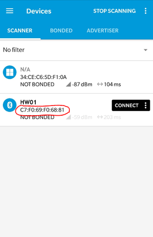
So the ESP32 BLE hardware address of my fitness band is C7:F0:69:F0:68:81, you will have a different set of numbers in the same format. Just make a note of it since we will need when we program our ESP32.
Obtaining the Service and Characteristic UUID of server
Okay, now we have identified our server using the BLE address but in order to communicate with it we need to speak the language of Service and characteristics, which you would understand if you had read the previous tutorial. In this tutorial I am using the write characteristic of my server (fitness band) to pair with it. So for pairing with the device we need the Service ad Characteristic UUID which can we can again obtain with the same application.
Just click on the connect button on your application and search for some write characteristics, where the application will display the service UUID and characteristic UUID. Mine is shown below

Here my Service UUID and Characteristic UUID is the same, but it does not have to be the same. Note down the UUID of your server. Mine was noted down as
Service UUID: 0000fee7-0000-1000-8000-00805f9b34fb

Characteristic UUID: 0000fee7-0000-1000-8000-00805f9b34fb
It is not mandatory to use the write characteristics; you can use any valid service and characteristic UUID of the server that is shown in the application.

Programming the ESP32 to acts as a client for Proximity Switch Application
The idea of the program is to make the ESP32 to act as a client that keeps scanning for Bluetooth devices when it finds our server (fitness band) it verifies the hardware ID and it will toggle the light through the GPIO pin 13. Well okay!!, but there is one problem with that. All BLE servers will have a range of 10 meters which is a bit too much. So if we are trying to make proximity switch to turn on light of open a door this range is very high.
To reduce the range of the BLE server we can use the pairing option. A BLE server and client will be remained paired only if both are within a distance of 3-4 Meters. That’s perfect for our application. So, we make the ESP32 not only to discover the BLE server but also to connect to it and make sure if it remains paired. As long as they are paired the AC lamp will remain on, when the range exceed the pairing will be lost and the lamp will be turned off. The complete ESP32 BLE example program to do the same is given at the end of this page. Below here, I will break the code into small snippets and try explaining them.
After including the header file, we inform the ESP32 about the BLE address, Service and characteristic UUID that we obtained though the nRF connect application as explained in above headings. The code looks like below
static BLEUUID serviceUUID("0000fee7-0000-1000-8000-00805f9b34fb"); //Service UUID of fitnessband obtained through nRF connect application
static BLEUUID    charUUID("0000fee7-0000-1000-8000-00805f9b34fb"); //Characteristic  UUID of fitnessband obtained through nRF connect application
String My_BLE_Address = "c7:f0:69:f0:68:81"; //Hardware Bluetooth MAC of my fitnessband, will vary for every band obtained through nRF connect application
Followed by that in the program we have the connectToserver and MyAdvertisedDeviceCallback which we will get back to later. Then inside the setup function, we initialize the serial monitor and make the BLE on ESP to scan for device. After the scan is complete for every BLE device discovered the function MyAdvertisedDeviceCallbacks is called.
We also enable active scan since we are powering the ESP32 with mains power, for battery application it is turned off to reduce current consumption. The Relay trigger pin is connected to GPIO 13 in our hardware, so we also declare that the GPIO pin 13 as output.
void setup() {
    Serial.begin(115200); //Start serial monitor
    Serial.println("ESP32 BLE Server program"); //Intro message

    BLEDevice::init("");
    pBLEScan = BLEDevice::getScan(); //create new scan
    pBLEScan->setAdvertisedDeviceCallbacks(new MyAdvertisedDeviceCallbacks()); //Call the class that is defined above
    pBLEScan->setActiveScan(true); //active scan uses more power, but get results faster
    pinMode (13,OUTPUT); //Declare the in-built LED pin as output
}
Inside the MyAdvertisedDeviceCallbacks function, we print line which will list the name and other information of the BLE devices that were discovered. We need the hardware ID of the BLE device that were discovered so that we can compare it with the desired one. So we use the variable Server_BLE_Address to get the address of the device and then also to convert it from type BLEAddress to string.
class MyAdvertisedDeviceCallbacks: public BLEAdvertisedDeviceCallbacks
{
    void onResult(BLEAdvertisedDevice advertisedDevice) {
      Serial.printf("Scan Result: %s \n", advertisedDevice.toString().c_str());
      Server_BLE_Address = new BLEAddress(advertisedDevice.getAddress());
      Scaned_BLE_Address = Server_BLE_Address->toString().c_str();
    }
};
Inside the loop function, we scan for 3 seconds and put the result inside foundDevices which is an object from BLEScanResults. If we find one or more than one device by scanning, we start to check if the discovered BLE address matches with the one that we entered in the program. If the match is positive and the device is not paired earlier we try paring with it using the connectToserver function. We have also used few Serial statements for understanding purpose.
  while (foundDevices.getCount() >= 1)
  {
    if (Scaned_BLE_Address == My_BLE_Address && paired == false)
    {
      Serial.println("Found Device :-)... connecting to Server as client");
       if (connectToserver(*Server_BLE_Address))
      {
Inside the connectToserver function we make use of the UUID to pair with the BLE server (fitness band). To connect with a server, the ESP32 has to act as a client, so we create a client by using the createClient() function and then connect to the address of the BLE server. Then we search for the service and characteristic using the UUID values and try connecting to it. When the connection is successful the function returns a true and if not it returns a false. Note that it is not mandatory to have service and characteristic UUID to pair with a server, it is done only for your understanding.
bool connectToserver (BLEAddress pAddress){
    BLEClient*  pClient  = BLEDevice::createClient();
    Serial.println(" - Created client");

    // Connect to the BLE Server.
    pClient->connect(pAddress);
    Serial.println(" - Connected to fitnessband");
    // Obtain a reference to the service we are after in the remote BLE server.
    BLERemoteService* pRemoteService = pClient->getService(serviceUUID);
    if (pRemoteService != nullptr)
    {
      Serial.println(" - Found our service");
      return true;
    }
    else
    return false;

    // Obtain a reference to the characteristic in the service of the remote BLE server.
    pRemoteCharacteristic = pRemoteService->getCharacteristic(charUUID);
    if (pRemoteCharacteristic != nullptr)
      Serial.println(" - Found our characteristic");
      return true;
}
If the connection is successful the GPIO pin 13 is made high and the control is sent outside the loop by using the break statement. The Boolean variable paired is also set to be true.
       if (connectToserver(*Server_BLE_Address))
      {
      paired = true;
      Serial.println("********************LED turned ON************************");
      digitalWrite (13,HIGH);
      break;
      }
After the pairing is successful and the GPIO pin is turned on we have to check if the device is still in range. Since, now the device is paired, the BLE scan service will no longer be able to see it. We will find it again only when the user leaves the area. So we simply have to scan for out BLE server and if we discover we have to set the GPIO pin to low as shown below
    if (Scaned_BLE_Address == My_BLE_Address && paired == true)
    {
      Serial.println("Our device went out of range");
      paired = false;
      Serial.println("********************LED OOOFFFFF************************");
      digitalWrite (13,LOW);
      ESP.restart();
      break;
    }
Working and Testing
Once you are ready with the program and the hardware set-up, simply upload the code to the ESP32 and arrange the whole set-up as shown below.
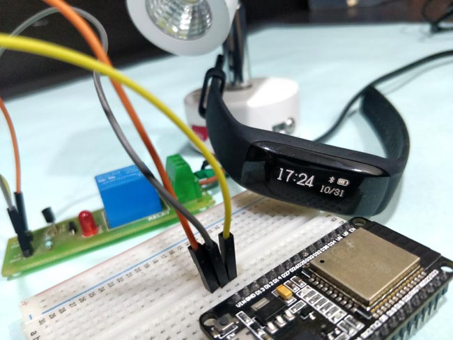
You should notice the Lamp getting turned on as soon as the fitness band (server) pairs with the ESP32. You can also check this by noticing the connection Bluetooth symbol on the fitness band. Once paired just try walking away from the ESP32 and when you cross 3-4 meters you will notice that the Bluetooth symbol on the watch disappears and connection is lost. Now, if you look at the lamp it will be turned off. When you walk back in the device gets paired again and light turns on. The complete working of the project can be found in the video below.
Hope you enjoyed the project and learnt something new on the way. If you had faced any problem in getting it to work, feel free to post the problem on forums or even on the comment section below
Complete Project Code
/*

 * Program to operate ESP32 in client mode and use fitness band as proximity switch

 * Program by: Aswinth Raj B

 * Dated: 31-10-2018

 * Website: www.circuitdigest.com

 * Reference: https://github.com/nkolban/esp32-snippets

 * //NOTE: The My_BLE_Address, serviceUUID and charUUID should be changed based on the BLe server you are using

 */

#include <BLEDevice.h> //Header file for BLE
static BLEUUID serviceUUID("0000fee7-0000-1000-8000-00805f9b34fb"); //Service UUID of fitnessband obtained through nRF connect application

static BLEUUID    charUUID("0000fee7-0000-1000-8000-00805f9b34fb"); //Characteristic  UUID of fitnessband obtained through nRF connect application

String My_BLE_Address = "c7:f0:69:f0:68:81"; //Hardware Bluetooth MAC of my fitnessband, will vary for every band obtained through nRF connect application

static BLERemoteCharacteristic* pRemoteCharacteristic;
BLEScan* pBLEScan; //Name the scanning device as pBLEScan

BLEScanResults foundDevices;
static BLEAddress *Server_BLE_Address;

String Scaned_BLE_Address;
boolean paired = false; //boolean variable to togge light

bool connectToserver (BLEAddress pAddress){


    BLEClient*  pClient  = BLEDevice::createClient();

    Serial.println(" - Created client");
    // Connect to the BLE Server.

    pClient->connect(pAddress);

    Serial.println(" - Connected to fitnessband");
    // Obtain a reference to the service we are after in the remote BLE server.

    BLERemoteService* pRemoteService = pClient->getService(serviceUUID);

    if (pRemoteService != nullptr)

    {

      Serial.println(" - Found our service");

      return true;

    }

    else

    return false;
    // Obtain a reference to the characteristic in the service of the remote BLE server.

    pRemoteCharacteristic = pRemoteService->getCharacteristic(charUUID);

    if (pRemoteCharacteristic != nullptr)

      Serial.println(" - Found our characteristic");
      return true;

}
class MyAdvertisedDeviceCallbacks: public BLEAdvertisedDeviceCallbacks

{

    void onResult(BLEAdvertisedDevice advertisedDevice) {

      Serial.printf("Scan Result: %s \n", advertisedDevice.toString().c_str());

      Server_BLE_Address = new BLEAddress(advertisedDevice.getAddress());


      Scaned_BLE_Address = Server_BLE_Address->toString().c_str();


    }

};

void setup() {

    Serial.begin(115200); //Start serial monitor

    Serial.println("ESP32 BLE Server program"); //Intro message
    BLEDevice::init("");

    pBLEScan = BLEDevice::getScan(); //create new scan

    pBLEScan->setAdvertisedDeviceCallbacks(new MyAdvertisedDeviceCallbacks()); //Call the class that is defined above

    pBLEScan->setActiveScan(true); //active scan uses more power, but get results faster
    pinMode (13,OUTPUT); //Declare the in-built LED pin as output

}
void loop() {
  foundDevices = pBLEScan->start(3); //Scan for 3 seconds to find the Fitness band

  while (foundDevices.getCount() >= 1)

  {

    if (Scaned_BLE_Address == My_BLE_Address && paired == false)

    {

      Serial.println("Found Device :-)... connecting to Server as client");

       if (connectToserver(*Server_BLE_Address))

      {

      paired = true;

      Serial.println("********************LED turned ON************************");

      digitalWrite (13,HIGH);

      break;

      }

      else

      {

      Serial.println("Pairing failed");

      break;

      }

    }


    if (Scaned_BLE_Address == My_BLE_Address && paired == true)

    {

      Serial.println("Our device went out of range");

      paired = false;

      Serial.println("********************LED OOOFFFFF************************");

      digitalWrite (13,LOW);

      ESP.restart();

      break;

    }

    else

    {

    Serial.println("We have some other BLe device in range");

    break;

    }

  }

}
Comments
can you please help me out.
hello sir,
can you help me out, i am not a arduino coder.
i am stuck at this. In the code, the loop never stops.
I want to trigger 2 relays using BLE and also set
the activetion distance area to 5meters from the esp32 so that it
triggers only when the BLE device is 5mtrs away.when it is detected
i want it to stay on, while running the code the relay switches on and
off every 2 seconds. hope you would fix it for me.
Thanks Anand.
(the code is:)
#include <BLEDevice.h> //Header file for BLE
static BLEUUID serviceUUID("0000fff0-0000-1000-8000-00805f9b34fb");
static BLEUUID charUUID("0000fff0-0000-1000-8000-00805f9b34fb");
String My_BLE_Address = "c1:b4:70:74:fb:66";
static BLERemoteCharacteristic* pRemoteCharacteristic;
BLEScan* pBLEScan;
BLEScanResults foundDevices;
static BLEAddress *Server_BLE_Address;
String Scaned_BLE_Address;
boolean paired = false;
boolean chkConnet = false;
bool connectToserver (BLEAddress pAddress)
{
BLEClient* pClient = BLEDevice::createClient();
Serial.println(" - Created client");
// Connect to the BLE Server.
pClient->connect(pAddress);
Serial.println(" - Connected");
BLERemoteService* pRemoteService = pClient->getService(serviceUUID);
if (pRemoteService != nullptr)
{
Serial.println(" - Found our service");
return true;
}
else
return false;
pRemoteCharacteristic = pRemoteService->getCharacteristic(charUUID);
if (pRemoteCharacteristic != nullptr)
Serial.println(" - Found our characteristic");
return true;
}
class MyAdvertisedDeviceCallbacks: public BLEAdvertisedDeviceCallbacks
{
void onResult(BLEAdvertisedDevice advertisedDevice)
{
Serial.printf("Scan Result: %s \n", advertisedDevice.toString().c_str());
Server_BLE_Address = new BLEAddress(advertisedDevice.getAddress());
Scaned_BLE_Address = Server_BLE_Address->toString().c_str();
}
};
void setup()
{
Serial.begin(115200);
Serial.println("Project-4");
BLEDevice::init("");
pBLEScan = BLEDevice::getScan();
pBLEScan->setAdvertisedDeviceCallbacks(new MyAdvertisedDeviceCallbacks());
pBLEScan->setActiveScan(true);
pinMode(12, OUTPUT);
pinMode(14, OUTPUT);
}
void loop()
{
foundDevices = pBLEScan->start(3);
Serial.println(chkConnet);
if(chkConnet == false)
{
while (foundDevices.getCount() >= 1)
{
if (Scaned_BLE_Address == My_BLE_Address && paired == false)
{
Serial.println("connecting .....");
if (connectToserver(*Server_BLE_Address))
{
paired = true;
Serial.println("ON");
if(chkConnet == false)
{
digitalWrite (12,HIGH);
digitalWrite (14,HIGH);
chkConnet = true;
Serial.println("On");
}
break;
}
else
{
Serial.println("Pairing failed");
break;
}
}
break;
}
}
while (foundDevices.getCount() == 0)
{
Serial.println("***************");
Serial.println(foundDevices.getCount());
Serial.println("out of range");
paired = false;
if(chkConnet == true)
{
digitalWrite (12,LOW);
digitalWrite (14,LOW);
chkConnet = false;
Serial.println("OFF");
}
ESP.restart();
break;
}
}
code inconsistency
Hi,
Thanks for sharing.
I noted that when only one device is in neighbourhood- works fine.
but when more (example 3) then it recognizes set addres , only if in scan results it was on last position. It can be first scan, but also 10th - just random - depends when different device broadcast its data.
could you propose fix? i am not so keen in coding to do it in elegant way... to be hones right now I do not have idea how to do it. :)
It should work with more devices
I do not understand your problem here, it should work the same even with multiple devices nearby
All devices will have a different address so you can look for the address of the device you need and control as such
Thanks for your reply.
Thanks for your reply.
Indeed, when I read my post now - it is also not clear for me.
lets start with example.
fitness tracker which I want to detect/switch addres is d3:51:08:d7:5f:88
look below behaviour from console: This is ok, but only because by coincidence, target device (the one choosen to "switch" - d3:etc is on last position.
but if I reset device and, by coincidence in scan results our target device is not on last position, program do not detect it, but scans again. scans again until it will be in results on last position, look on below output. Here it was necessary to scan 3 times. This is random of course, sometimes once i ok, sometimes close to ten:
so I think that program does not look into all scan results, but only to last one addres from all scanned.
hopefully it is clear now what I wanted to say :)
Now I get it, I did not test
Now I get it, I did not test for this when I built it. Anyways I am sure it should we possible to correct this with code, I will re-create the problem if I find time and let you know the solution
If you lack of time, do not
If you lack of time, do not look into this.
I made a dirty workaround somehow, and works for me.
I will not publish it , because it is for sure not elegant.
Just moved the comparison part to scan part.
Anyway , thanks for great post, with many ble details and explanation.
To be honest one thing is not clear for me.
Is it important if BLE device is paired with phone ? I mean important for being used in this scenario?
Makes it any difference?
I suspect yes, after you wrote that bluetooth rf power can be limited after pairing, than it is possible that when you come with paired phone in pocket, the range of fitness band will be low, and detecting Esp32 will not detect it from for example 5 meters.
I tried this, but with my bands I couldn't notice difference. But who knows? ...
What is your opinion?
Paring should not be a problem
No, it is not important for the BLE device to be paired to your phone. Your BLE device just has to be in advertising mode and no this will also not affect the range
Ok, this was my observation -
Ok, this was my observation - no change in range.
Thank you.
Hi,
Hi,
I am trying to modify this programme, and have it switch on the Light based on RSSI strenght.
I am having trouble only measuring the RSSI of the specific device, and making decisions based on that. Instead it is looking at all the BLE devices.
Could you provide me with any help to solve this problem?
Thansk

sometimes esp32 is loosing connection to my mi1s band, so it doing a loop in code while GPIO is LOW. not so long but for end using is seems like an old disco - light is blinking.
how do you think it is mi1s trouble? or maybe other application blocking data channel?