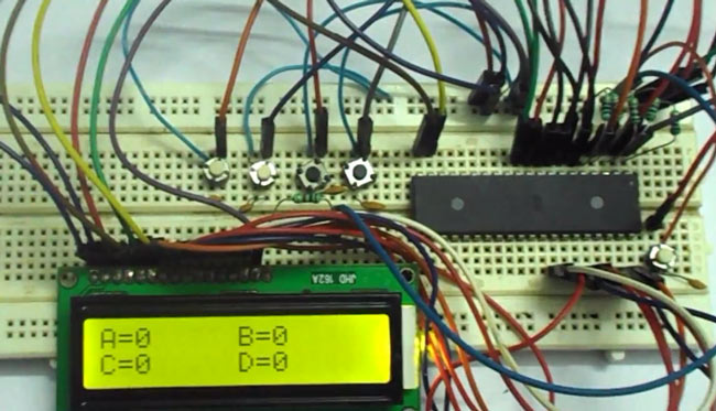
Whenever we go to vote for elections we come to see electronic voting machines. In this project we are going to design and develop a simple voting machine by using ATmega32A microcontroller. Although we can use the controller to get more than 32 people voting machine, to keep everything simple we are going to make a voting system for a size of four people.We will have four buttons for four people and whenever a button is pressed, a vote goes for the corresponding person and the number of votes each person gets shown on LCD.
Components Required
Hardware:
ATMEGA32
Power supply (5v)
AVR-ISP PROGRAMMER
JHD_162ALCD (16x2 LCD)
100nF capacitor (five pieces), 100uF capacitor (connected across power supply)
button(five pieces),
10KΩ resistor (five pieces).
Software:
Atmel studio 6.1
progisp or flash magic.
Circuit Diagram and Working Explanation
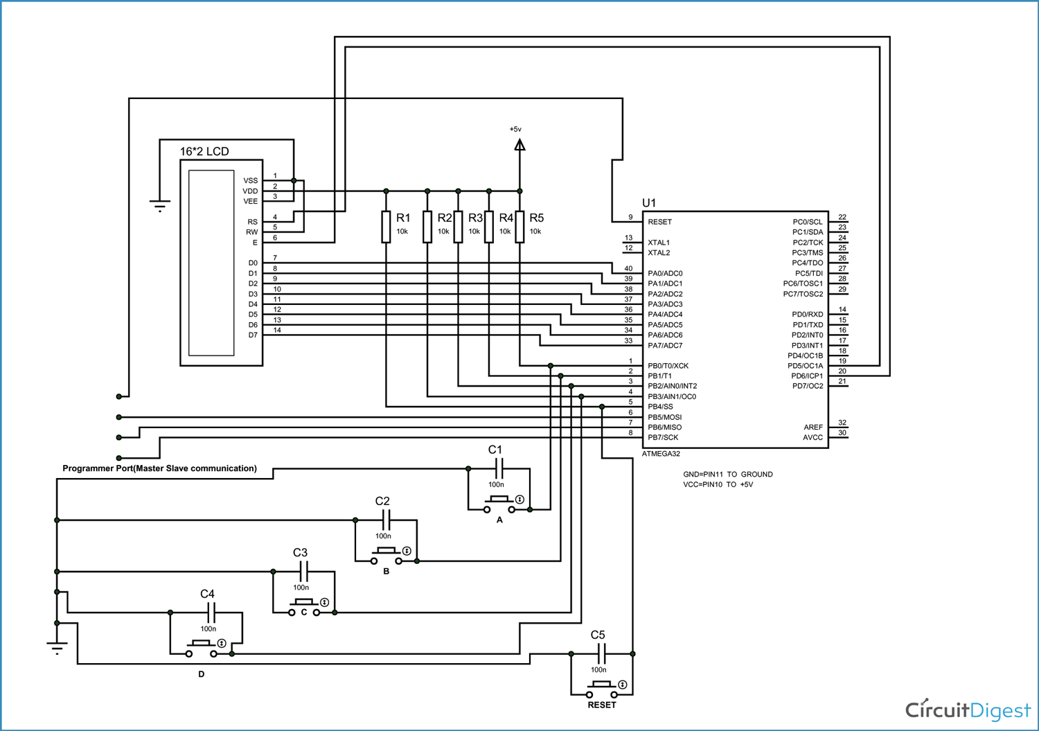
As shown in the above electronic voting machine circuit, PORTA of ATMEGA32 microcontroller is connected to data port of 16x2 LCD. Here one should remember to disable the JTAG communication in PORTC of ATMEGA by changing the fuse bytes, if one wants to use the PORTC as a normal communication port. In 16x2 LCD, there are 16 pins over all if there is a back light, if there is no back light there will be 14 pins. One can power or leave the back light pins. Now in the 14 pins there are 8 data pins (7-14 or D0-D7), 2 power supply pins (1&2 or VSS&VDD or gnd&+5v), 3rd pin for contrast control (VEE-controls how thick the characters should be shown), 3 control pins (RS&RW&E).
In the circuit, you can observe that I have only taken two control pins as this give the flexibility of better understanding. The contrast bit and READ/WRITE are not often used so they can be shorted to ground. This puts LCD in highest contrast and read mode. We just need to control ENABLE and RS pins to send characters and data accordingly.
The connections which are done for LCD are given below:
PIN1 or VSS - ground
PIN2 or VDD or VCC - +5v power
PIN3 or VEE - ground (gives maximum contrast best for a beginner)
PIN4 or RS (Register Selection) - PD6 of uC
PIN5 or RW (Read/Write) - ground (puts LCD in read mode eases the communication for user)
PIN6 or E (Enable) - PD5 of uC
PIN7 or D0 - PA0 of uC
PIN8 or D1 - PA1 of uC
PIN9 or D2 - PA2 of uC
PIN10 or D3 - PA3 of uC
PIN11 or D4 - PA4 of uC
PIN12 or D5 - PA5 of uC
PIN13 or D6 - PA6 of uC
PIN14 or D7-- PA7 of uC
In the circuit you can see we have used 8bit communication (D0-D7) however this is not a compulsory. We can use 4bit communication (D4-D7) but with 4 bit communication program becomes a bit complex so I just went with 8 bit communication.
So from mere observation of above table we are connecting 10 pins of LCD to controller in which 8 pins are data pins and 2 pins for control. There are five buttons present here, four for incrementing the votes of candidates and fifth is for resetting the candidate’s votes to zero.
The capacitors present here is for nullifying the bouncing effect of buttons. If they are removed the controller might count more than one each time the button is pressed. The resistors connected for pins are for limiting the current, when the button is pressed to pull down the pin to the ground.
Whenever a button is pressed, The corresponding pin of controller gets pulled down to ground and thus the controller recognizes that certain button is pressed and corresponding action to be taken, it may be incrementing the candidate votes or resetting of votes depending on button pressed.
When the button representing a corresponding person is pressed, the controller picks it and increments the corresponding person number inside its memory after increment it shows the corresponding persons score on the 16x2 LCD display.
The working of this microcontroller based electronic voting machine is explained in step by step of C code down below,
Complete Project Code
/*

C Program for AVR Microcontroller Based Electronic Voting Machine

*/

#include <avr/io.h> //header to enable data flow control over pins

#define F_CPU 1000000 //telling controller crystal frequency attached

#include <util/delay.h> //header to enable delay function in program

#define    E   5 //giving name “enable”  to 5th pin of PORTD, since it Is connected to LCD enable pin

#define RS  6 //giving name “registerselection” to 6th pin of PORTD, since is connected to LCD RS pin


void send_a_command(unsigned char command);

void send_a_character(unsigned char character);

int main(void)

{

    DDRA = 0xFF; //putting porta and port d as output pins

    DDRD = 0xFF;

    _delay_ms(50); //giving delay of 50ms

    DDRB = 0; //Taking portB as input.


    int16_t COUNTA = 0; // person1 votes storing memory

    char SHOWA [16]; // person1 votes displaying character on LCD

    int16_t COUNTB = 0;  // person2 votes storing memory

    char SHOWB [16]; // person2 votes displaying character on LCD

    int16_t COUNTC = 0; // person3 votes storing memory

    char SHOWC [16]; // person3 votes displaying character on LCD

    int16_t COUNTD = 0; // person4 votes storing memory

    char SHOWD [16]; //person4 votes displaying character on LCD


    send_a_command(0x01);  //Clear Screen 0x01 = 00000001

    _delay_ms(50);

    send_a_command(0x38); //telling lcd we are using 8bit command /data mode

    _delay_ms(50);

    send_a_command(0b00001111); //LCD SCREEN ON and courser blinking


    while(1)

    {

        send_a_string ("A="); // displaying person1 name

        send_a_command(0x80 + 2); // shifting cursor  to 3rd shell

        itoa(COUNTA,SHOWA,10); // command for putting variable number in LCD(variable number, in which character to replace, which base is variable(ten here as we are counting number in base10))

        send_a_string(SHOWA); //telling the display to show character(replaced by variable number) of first person after positioning the courser on LCD.

        send_a_command(0x80 + 8); // shifting cursor  to 9th shell

        send_a_string ("B="); // displaying person2name

        send_a_command(0x80 + 10); //shifting cursor  to 11th shell

        itoa(COUNTB,SHOWB,10); //command for putting variable number in LCD(variable number, in which character to replace, which base is variable(ten here as we are counting number in base10))

        send_a_string(SHOWB); ); //telling the display to show character(replaced by variable number) of second person after positioning the courser on LCD.

        send_a_command(0x80 + 0x40 + 0); // shifting cursor  to 1st  shell  of second line

        send_a_string ("C="); // displaying person3 name

        send_a_command(0x80 + 0x40 + 2); //shifting cursor  to 3rd  shell  of second line

        itoa(COUNTC,SHOWC,10);

        send_a_string(SHOWC);

        send_a_command(0x80 + 0x40 + 8); // shifting cursor  to 9th   shell  of second line

        send_a_string ("D="); //displaying person4name

        send_a_command(0x80 + 0x40 + 10); //shifting cursor  to 11th   shell  of second line

        itoa(COUNTD,SHOWD,10);

        send_a_string(SHOWD);

        send_a_command(0x80 + 0); // shifting cursor  to 0th position

        if (bit_is_clear(PINB,0))//when button one  is pressed

        {

            COUNTA++; // increment the vote memory of first person by one

        }

        if (bit_is_clear(PINB,1)) // when button 2  is pressed

        {

            COUNTB++; // increment the vote memory of second person by one

        }

        if (bit_is_clear(PINB,2)) // when button 3  is pressed

        {

            COUNTC++; // increment the vote memory of third person by one

        }

        if (bit_is_clear(PINB,3)) // when button 4  is pressed

        {

            COUNTD++; // increment the vote memory of fourth person by one

        }

        if (bit_is_clear(PINB,4)) // when button 5  is pressed

        {

            COUNTA=COUNTB=COUNTC=COUNTD=0; //clearing vote memory of all persons.

        }

    }

    }


    void send_a_command(unsigned char command)

    {

        PORTA = command;

        PORTD &= ~ (1<<RS); //putting 0 in RS to tell lcd we are sending command

        PORTD |= 1<<E; //telling lcd to receive command /data at the port

        _delay_ms(50);

        PORTD &= ~1<<E; //telling lcd we completed sending data

        PORTA= 0;

    }


    void send_a_character(unsigned char character)

    {

        PORTA= character;

        PORTD |= 1<<RS; //telling LCD we are sending data not commands

        PORTD |= 1<<E; //telling LCD to start receiving command/data

        _delay_ms(50);

        PORTD &= ~1<<E; //telling lcd we completed sending data/command

        PORTA = 0;

    }

}
Comments
hi i have be following up
hi i have be following up with ur demos .please how then can you pass a string as arguments of a function?cause i want to control multiple pwms by sending different duty as a string at a time
like
void setpm( unit8_t dutya ,unit8_t dutyb)
{ OCRO=dutya;
OCR2=dutyb;
}
i can type on my lcd and press a key like enter .
Send the brief detail on your
Share the brief detail of your project i will help you.
i have made an led display
i have made an led display with two colours leds using two pwm pins .pinD7;pinD3 on the atmega32. i want a way to change the duty of each led by passing the commands using my keyboard .so that at one i can make one colour brighter than the other. thanks
Can you help me please?
Iam try to do the same thing that you already here did. But with xmega board in Atmel studio 7.0. And i have a problem with the code that you already did here. Can you help me with that???thank you
question!!!
hi.i wanted to simulate the code in CV-avr and make a .cof file for Proteus.
could u please help me?
not run program
send_a_string ("a=")
itoa(COUNTA,SHOWA,10)
what is the function of these??????/
What is the function snippet
What is the function snippet for send_a_string.


May I know what is the coding for "send_a_string ("A=")". Thank you.