

In our previous RC Phase Shift Oscillator and Wein Bridge Oscillator tutorials, we get fair idea about what is an Oscillator. An oscillator is a mechanical or electronic construction which produces oscillation depending on few variables. A proper good oscillator produces stable frequency.
In case of RC (Resistor-Capacitor) or RLC (Resistor-Inductor-Capacitor) Oscillators, they are not good choice where stable and accurate oscillations are needed. The temperature changes affect the load and power supply line which in turn affects the stability of the Oscillator circuit. The stability can be improved to a certain level in case of RC and RLC circuit, but still the improvement is not sufficient in specific cases.
In such situation, the Quartz Crystal is used. Quartz is mineral composed of silicon and Oxygen atoms. It reacts when a voltage source applied to quartz crystal. It produces a characteristic, identified as Piezo-electric effect. When voltage source is applied across it, it will change shape and produce mechanical forces, and the mechanical forces revert back, and produce electrical charge.
As it convert energy electrical to mechanical and mechanical to electrical it is referred as Transducers. These changes produce very stable vibration, and as a Piezo-electric effect produces the stable oscillations.
Quartz Crystal and its Equivalent Circuit

This is the symbol of Crystal Oscillator. The quartz crystal is made from thin piece of quartz wafer tightly fitted and controlled between two parallel metalized surfaces. The metalized surfaces are made for electrical connections, and the quartz physical size and density also the thickness is tightly controlled as the changes in shape and size directly effect in the oscillation frequency. Once it is shaped and controlled, the frequency produced is fixed, the fundamental frequency cannot be changed into other frequencies. This specific frequency for the specific crystal is called characteristic frequency.
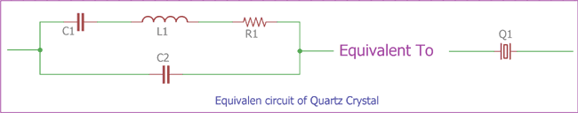
In the upper image, left circuit represents the equivalent circuit of Quartz Crystal, shown in the right side. As we can see, 4 passive components are used, two capacitor C1 and C2 and one Inductor L1, Resistor R1. C1, L1, R1 is connected in series and the C2 connected in parallel.
The series circuit which consists one capacitor, one resistor and one inductor, symbolize the controlled behavior and stable operations of the Crystal and the parallel capacitor, C2 represents the parallel capacitance of the circuit or the equivalent crystal.
At the operating frequency the C1 resonate with the inductance L1. This operating frequency is referred as crystals series frequency (fs). Due to this series frequency a secondary frequency point recognized with the parallel resonance. L1 and C1 also resonate with the parallel capacitor C2. The parallel Capacitor C2 often describes as the name of C0 and called Shunt Capacitance of a Quartz Crystal.
Crystal Output Impedance against Frequency
If we apply reactance formula across two capacitors, then, for the series capacitor C1, the capacitive reactance will be:-
XC1 = 1 / 2πfC1
Where,
F = Frequency and C1 = value of the series capacitance.
Same formula applies for the Parallel capacitor too, the capacitive reactance of the parallel capacitor will be:-
XC2 = 1 / 2πfC2
Where,
F = Frequency and C2 = value of the parallel capacitance.
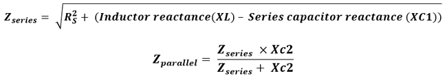
In case of calculating the series impedance and parallel impedance the formulas will be:-
If we see the relationship graph in between Output impedance vs Frequency we will see the changes in impedance.
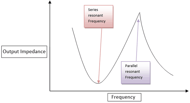
In the upper image we see the impedance curve of the crystal oscillator and also see that, how this slope changes when frequency changes. There are two points one is series resonant frequency point and the other one is parallel resonant frequency point.
At the series resonant frequency point the impedance is became minimum. The series capacitor C1 and the series Inductor L1 create a series resonance which is equal to series resistor.
So, at this series resonant frequency point, the following things will happen:-
- The Impedance is minimum compared in other frequency times.
- Impedance is equal to the series resistor.
- Below this point the crystal acts as a capacitive form.
Next the frequency gets changed and the slope slowly increased to the maximum point at parallel resonant frequency, at this time, before reaching the parallel resonant frequency point the crystal act as a series inductor.
After reaching the parallel frequency point the impedance slope reaches maximum in value. The parallel capacitor C2 and the Series Inductor create a LC tank circuit and thus the output impedance became high.
This is how the crystal behaves as inductor or like a capacitor in series and parallel resonance. Crystal can operate in this both resonance frequencies but not at the same time. It is need to be tune at any specific one to operate.
Crystal Reactance against Frequency
The series Reactance of the circuit can be measured using this formula:-
XS = R2 + (XL1 – XC1)2
Where, R is the value of resistance
Xl1 is the series inductance of the circuit
Xc1 is the series capacitance of the circuit.
Parallel capacitive reactance of the circuit will be:-
XCP = -1 / 2πfCp
The parallel reactance of the circuit will be :-
Xp = Xs * Xcp / Xs + Xcp
If we see the graph it will look like this:-
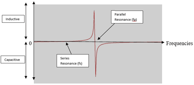
As we can see in the upper graph that the series reactance at the point of series resonance is inversely proportional to C1, at the point from fs to fp the crystal act as inductive because at this point, two parallel capacitance become negligible.
On the other hand, the crystal will be at capacitive form when the frequency is outside of the fs and fp points.
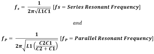
We can calculate the Series Resonant Frequency and Parallel Resonant frequency using this two formulas –
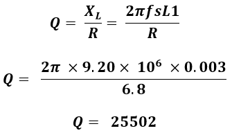
Q Factor for Quartz crystal:
Q is the short form of Quality. It is an important aspect of quartz crystal resonance. This Q factor determines Crystal’s frequency stability. In general, the Q factor of a crystal has a range from 20, 000 to more than 100,000. Sometimes, the Q factor of a crystal is more than 200,000 also observable.
Q factor of a crystal can be calculated using the following formula –
Q = XL / R = 2πfsL1 / R
Where, XL is inductor Reactance and R is the Resistance.
Quartz Crystal Oscillator Example with Calculation
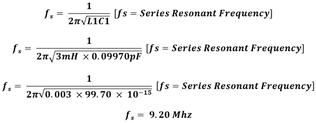
We will calculate a quartz crystals series resonant frequency, parallel resonant frequency and the Quality factor of the crystal when the following points are available-
R1 = 6.8R
C1 = 0.09970pF
L1 = 3mH
And C2 = 30pF
Series resonant frequency of the crystal is –
Crystal’s parallel resonant frequency, fp is –
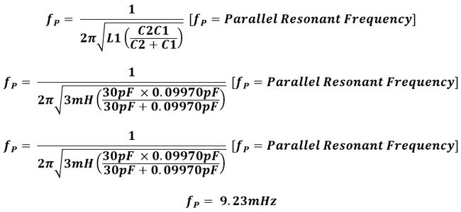
Now, we can understand that the series resonant frequency is 9.20 MHz and the parallel resonant frequency is 9.23 MHz
The Q factor of this crystal will be-

Colpitts Crystal Oscillator
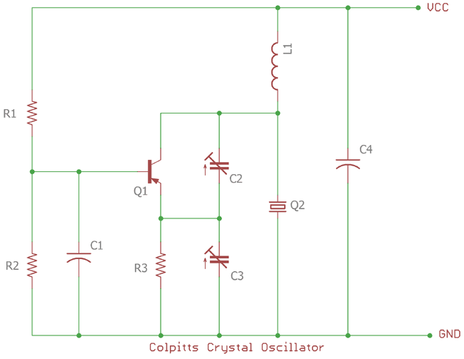
Crystal oscillator circuit constructed using bipolar transistor or various types of FETs. In the upper image, a colpitts oscillator is shown; the capacitive voltage divider is used for feedback. The transistor Q1 is in common emitter configuration. In the upper circuit R1 and R2 is used for the biasing of the transistor and C1 is used as bypass capacitor which protect the base from RF noises.
In this configuration, crystal will act as a shunt due to the connection from collector to ground. It’s in parallel resonant configuration. Capacitor C2 and C3 is used for feedback. The crystal Q2 is connected as parallel resonant circuit.
The output amplification is low in this configuration for avoiding excess power dissipation in the crystal.
Pierce Crystal Oscillator
Another configuration used in quartz crystal oscillator, where the Transistor is changed to a JFET for the amplification where the JFET is in very high input impedances when the crystal is connected in Drain to Gate using a capacitor.
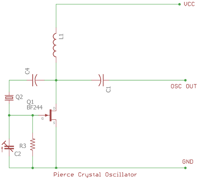
In the upper image a Pierce Crystal Oscillator circuit is shown. The C4 provides the necessary feedback in this oscillator circuit. This feedback is positive feedback which is 180 degree phase shift at the resonant frequency. R3 control the feedback and the crystal provides the necessary oscillation.
Pierce crystal oscillator needs minimum components count and due to this it is a preferable choice where space is limited. Digital clock, timers, and various type of Watches use pierce crystal oscillator circuit. The Output sine wave amplitude peak to peak value is limited by the JFET voltage range.
CMOS Oscillator
A basic oscillator which use parallel-resonant crystal configuration can be made using CMOS inverter. The CMOS inverter can be used for achieving required amplitude. It consists inverting Schmitt trigger like 4049, 40106 or Transistor-Transistor logic (TTL) chip 74HC19 etc.
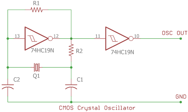
In the upper image 74HC19N used which acting as a Schmitt trigger in inverting configuration. The crystal will provide necessary oscillation in series resonance frequency. R1 is the feedback resistor for the CMOS and provide high Q factor with high gain capabilities. The second 74HC19N is booster to provide sufficient output for the load.
The inverter operate at 180 degree phase shift output and the Q1, C2, C1 provide additional 180 degree phase shift. During the oscillation process the phase shift always remain 360 degree.
This CMOS crystal oscillator provides square wave output. The maximum output frequency is fixed by the switching characteristic of the CMOS inverter. The output frequency can be changed using the Capacitors value and the Resistor value. C1 and C2 needs to be the same in values.
Providing Clock to Microprocessor using Crystals
As various use of quartz crystal oscillator includes Digital watches, Timers etc, it is also a suitable choice for providing stable oscillation clock across microprocessor and CPUs.
Microprocessor and CPU needs stable clock input for operation. Quartz crystal is widely used for these purposes. Quartz crystal provides high accuracy and stability compared to other RC or LC or RLC oscillators.
In general the clock frequency is used for microcontroller or CPU is ranged from KHz to Mhz. This clock frequency determines how fast the processor can process data.
To achieve this frequency a series crystal used with two same value capacitors network is used across the oscillator input of the respective MCU or CPU.
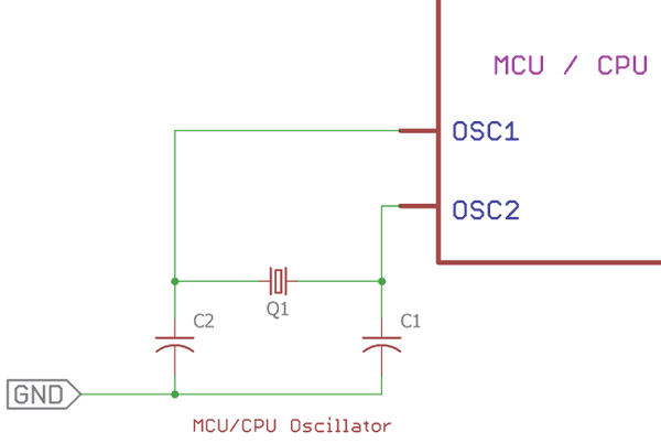
In this image, we can see that a Crystal with two capacitor forms a network and connected across Microcontroller unit or Central processing unit via OSC1 and OSC2 input pin. Generally all microcontroller or processor consist this two pin. In some cases there are two types of OSC pins available. One is for primary oscillator for generating the clock and other for the secondary oscillator which is used for other secondary works where secondary clock frequency is needed. The capacitor value range from 10pF to 42 pF, anything in between but 15pF, 22pF, 33pF is used widely.
Thanks for the explanation, really useful
Thank you for the excellent article. Please note that"74HC19N" is not a valid integrated circuit type number. You probabaly meant "74HC14N."

I purchased a couple 45mhz clock oscillators over the internet to build a noisey circuit and they have 3 leads to solder to the PCP what lead is what?