
Atmega16 is a low cost 8 bit microcontroller and comes with more number of GPIO’s than its previous version of microcontrollers. It has all the commonly used communication protocols like UART, USART, SPI and I2C. It has wide applications in robotics, automobile and automation industries because of its wide community support and simplicity.
Atmega16 doesn’t support any of the wireless communication protocols such as Wi-Fi and Bluetooth which limits its application areas in domain like IoT. To overcome this limitation other controllers can be interfaced which has wireless protocols. There are number of controllers which supports wireless protocols like widely used ESP8266,
Today we will interface Atmega16 with ESP8266 NodeMCU to make it communicate wirelessly through internet. ESP8266 NodeMCU is widely used WiFi module with community support and easily available libraries. Also ESP8266 NodeMCU is easily programmable with Arduino IDE. ESP8266 can be interfaced with any microcontroller:
- ESP8266 Interfacing with ARM7-LPC2148- Creating a Webserver to control an LED
- Connecting ESP8266 with STM32F103C8: Creating a Webserver
- Interfacing ESP8266 with PIC16F877A Microcontroller
- Sending Email using Arduino and ESP8266 WiFi Module
In this tutorial, email will be sent using ESP8266 NodeMCU module and Atmega16. The instructions will be given by Atmega16 and when ESP8266 receives the instructions, it will send an email to selected email recipient. ATmega16 and ESP8266 NodeMCU will communicate over UART serial communication. Although any communication protocol can be used to interface ATmega16 and ESP8266 NodeMCU such as SPI, I2C or UART.
Things to remember before starting
Note that the Atmega16 microcontroller used in this project works on 5V logic level whereas ESP8266 NodeMCU works on 3.3V logic level. The logic levels of both the microcontrollers are different which can cause some miscommunication between Atmega16 and ESP8266 NodeMCU or there can also be data loss if proper logic level is not maintained.
However after going through the datasheets of both microcontroller, we found that we can interface without any logic level shifting as all pins of ESP8266 NodeMCU are tolerant from voltage level up to 6V. So it is fine going ahead with 5V logic level. Also, datasheet of Atmega16 clearly states that the voltage level above 2V is considered as Logic Level ‘1’ and ESP8266 NodeMCU runs on 3.3 V, it means if ESP8266 NodeMCU is transmitting 3.3V then Atmega16 can take it as logic level ‘1’. So communication will be possible without using logic level shifting. Although you are free to use logic level shifter from 5 to 3.3V.
Check all the ESP8266 related projects here.
Components Required
- ESP8266 NodeMCU Module
- Atmega16 Microcontroller IC
- 16Mhz Crystal Oscillator
- Two 100nF Capacitors
- Two 22pF Capacitors
- Push Button
- Jumper Wires
- Breadboard
- USBASP v2.0
- Led(Any Color)
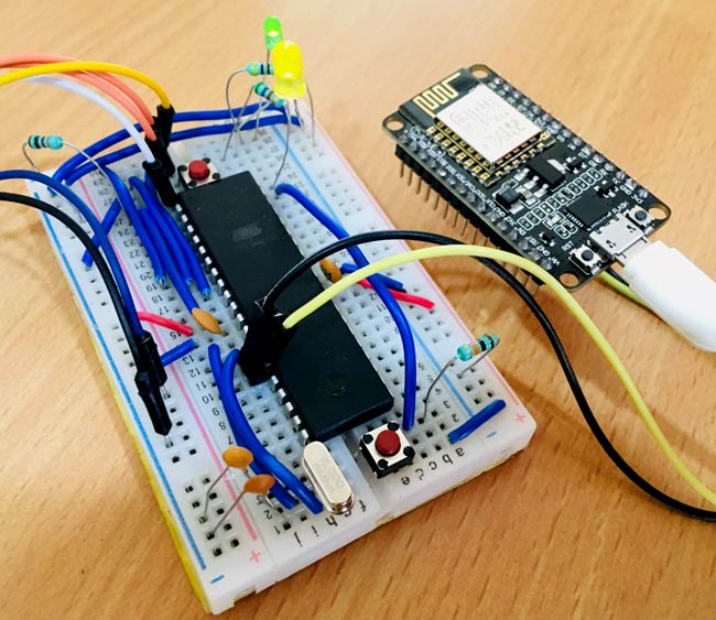
Circuit Diagram

Setting Up SMTP2GO Server for sending Email
Before start programming we need a SMTP server to send mail through ESP8266. There are plenty of SMTP servers available online. Here, smtp2go.com will be used as SMTP server.
So before writing code, the SMTP username and password will be required. To get these two credentials follow the steps below which will cover setting up SMTP server for successfully sending emails.
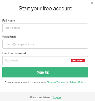
Step 1:- Click on “Try SMTP2GO Free” to register with a free account.

Step 2:- A window will pop up, where you need to enter some credential like name, email id and password.
Step 3:- After sign up, you will receive an activation request on the entered Email. Activate your account from the verify link in email and then login using your email id and password.
Step 4:- Once you log in, you will get your SMTP Username and SMTP Password. Remember or copy these to your notepad for further use. After this click on ‘finish’.

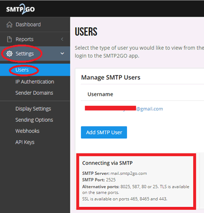
Step 5:- Now on the left access bar, click on “Settings” and then on “Users”. Here, you can see the information regarding to the SMTP Server and PORT number. It is usually as follows:
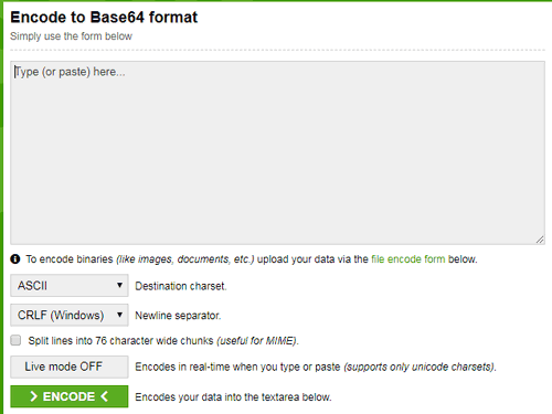
Encode Username and Password
Now we have to change Username and Password in base64 encoded format with ASCII character set. For converting the Email and Password in base64 encoded format use a website called BASE64ENCODE (https://www.base64encode.org/). Copy the encoded username and password, for further use:
After finishing these steps proceed for the programming of ESP8266 NodeMCU and Atmega16 IC.
Programming AVR Microcontroller Atmega16 and ESP8266
Programming will include two programs, one for Atmega16 to act as sender of instructions and second one for ESP8266 NodeMCU to act as receiver of instructions. Both the programs are given at the end of this tutorial. Arduino IDE is used to burn ESP8266 and USBasp programmer and Atmel Studio is used to burn Atmega16.
One push button and LED is interfaced with Atmega16 so that when we press the push button the Atmega16 will send instructions to NodeMCU and NodeMCU will send email accordingly. The LED will show the status of data transmission. So let’s start Programming Atmega16 and then ESP8266 NodeMCU.

Programming ATmega16 for Sending Email
Start with defining operating frequency and including all libraries necessary. The library used comes with Atmel Studio Package.
#define F_CPU 16000000UL
#include<avr/io.h>
#include<util/delay.h>
#include <stdlib.h>
#include <stdio.h>
After this, the baud rate has to be defined in order to communicate with ESP8266. Note that the baud rate has to be similar for both controllers i.e. Atmega16 and NodeMCU. In this tutorial, the baudrate is 9600.
#define BAUD_PRESCALE (((F_CPU / (USART_BAUDRATE * 16UL))) - 1)
The two registers UBRRL and UBRRH will be used to load baud rate values. The lower 8-bits of baud rate will load in UBRRL and the upper 8-bits of baud rate will load in UBRRH. For simplicity, make function of UART initialisation where the baud rate will be passed by value. The UART initialisation function will include:
- Setting Transmission and Reception bits in register UCSRB.
- Selecting 8-bit character sizes in register UCSRC.
- Loading of lower and upper bits of Baud rate in UBRRL and UBRRH register.
void UART_init(long USART_BAUDRATE)
{
       UCSRB |= (1 << RXEN) | (1 << TXEN);
       UCSRC |= (1 << URSEL) | (1 << UCSZ0) | (1 << UCSZ1);
       UBRRL = BAUD_PRESCALE;
       UBRRH = (BAUD_PRESCALE >> 8);
}
Next step will be setting up function for transmitting characters. This step includes waiting for empty buffer to finish and then load char value to UDR register. The char will be passed in function only.
            void UART_TxChar(char c)
        {
       while (! (UCSRA & (1<<UDRE)));
       UDR = c;
         }
Instead of transferring characters, make a function to send strings like below.
void UART_sendString(char *str)
        {
       unsigned char s=0;

       while (str[s]!=0)
        {
        UART_TxChar(str[s]);
              s++;
            }
          }
In main() function, call UART_init() to start the transmission. And do echo test by sending TEST string to NodeMCU.
            UART_init(9600);
UART_sendString("TEST");
Start configuring GPIO pin for LED and Push Button.
         DDRA |= (1<<0);
         DDRA &= ~(1<<1);
         PORTA |= (1<<1);
If push button is not pressed then keep the LED turned ON and if the Push Button is pressed then Start transmitting “SEND” command to NodeMCU and make LED turned OFF.
                     if(bit_is_clear(PINA,1))
              {
                     PORTA |= (1<<0);
                     _delay_ms(20);
              }
              else
              {
                      PORTA &= ~(1<<0);
                     _delay_ms(50);
                     UART_sendString("SEND");
                     _delay_ms(1200);
              }
Programming ESP8266 NodeMCU
Programming NodeMCU includes reception of command from Atmega16 and Sending Email using One SMTP server.
Firstly, include the WIFI library as internet will be used to send email. Define your WIFI ssid and password for successful connection. Also define the SMTP server.
#include <ESP8266WiFi.h>
const char* ssid = "xxxxxxxxxxxx";
const char* password = "xxxxxxxxxxx";
char server[] = "mail.smtp2go.com";
In setup() function, Set the baud rate similar to Atmega16 baud rate as 9600 and connect to WIFI and display IP address.
 Serial.begin(9600);
 Serial.print("Connecting To: ");
 Serial.println(ssid);
 WiFi.begin(ssid, password);
 while (WiFi.status() != WL_CONNECTED)
 {
 delay(500);  Serial.print(".");
 }
In loop() function, read the receiving bytes at Rx pin and convert it to string form.
if ( Serial.available() > 0 ) {
    while (Serial.available() > 0 && index1 < 6)
    {
      delay(100);
      inChar = Serial.read();
      inData[index1] = inChar;
      index1++;
      inData[index1] = '\0';
    }
    variable.toUpperCase();
    for (byte  i = 0 ; i < 6 ; i++) {
      variable.concat(String(inData[i]));
    }
    Serial.print("variable is = "); Serial.println(variable);
    Serial.print("indata is = "); Serial.println(inData);
    delay(20);
  }
String  string = String(variable);
If the receiving command is matched then send email to the recipient by calling sendEmail() function.
  if (string == "SEND") {
    sendEmail();
    Serial.print("Mail sent to:"); Serial.println(" The recipient");
    Serial.println("");
  }
It is very important to setup SMTP server and without doing this, no emails can be sent. Also note that while communication, set baud rate similar for both the controllers.
So this is how ESP8266 can be interfaced with AVR microcontroller to enable it for IoT communications. Also check the working Video given below.
Complete Project Code
ESP Code for Sending Email using Atmega16
/* Sending Email using Atmega16 and NodeMCU
* Circuit Digest(www.circuitdigest.com) */
#include <ESP8266WiFi.h>
const char* ssid = "xxxxxxxxx"; // Enter the SSID of your WiFi Network. *******************
const char* password = "xxxxxxxxxx"; // Enter the Password of your WiFi Network. ********************
char server[] = "mail.smtp2go.com"; // write SMTP server address ******************
WiFiClient Client; //define wifi client as client
void setup() {
delay(1000);
Serial.begin(9600); // set baudrate as 9600 similar to Atmega16
Serial.println("");
Serial.print("Connecting To: ");
Serial.println(ssid);
WiFi.begin(ssid, password); // connect to WIFI
while (WiFi.status() != WL_CONNECTED)
{
delay(500);
Serial.print(".");
}
Serial.println("");
Serial.println("WiFi Connected.");
Serial.print("IP address: ");
Serial.println(WiFi.localIP());
}
void loop() {
char inChar = 0;
char inData[6] = ""; // data length of 6 characters
String variable = "";
String variable1 = "";
int index1 = 0;
if ( Serial.available() > 0 ) { // Read from Rx from atmega16
while (Serial.available() > 0 && index1 < 6) // read till 6th character
{
delay(100);
inChar = Serial.read(); // start reading serilly and save to variable
inData[index1] = inChar;
index1++;
inData[index1] = '\0'; // Add a null at the end
}
variable.toUpperCase(); // convert to uppercase
for (byte i = 0 ; i < 6 ; i++) {
variable.concat(String(inData[i])); // concat strings
}
Serial.print("Variable = "); Serial.println(variable); // debug and print incoming data
delay(20);
}
String string = String(variable); // string used to compare
if (string == "SEND") { // if received data is "SEND" then send email
sendEmail(); // send email by calling function
Serial.print("Mail sent to:"); Serial.println(" The recipient"); // debug if sent
Serial.println("");
}
}
byte sendEmail()
{
if (Client.connect(server, 2525) == 1) // connect to smtp server with port address 2525
{
Serial.println(F("connected to server"));
}
else
{
Serial.println(F("connection failed"));
return 0;
}
if (!emailResp()) // if connection failed return now
return 0;
//
Serial.println(F("Sending EHLO"));
Client.println("EHLO www.example.com"); // Send command EHLO previosly it was HELO********************
if (!emailResp())
return 0;
Serial.println(F("Sending auth login"));
Client.println("AUTH LOGIN");
if (!emailResp())
return 0;
//
Serial.println(F("Sending User"));
// Change this to your base64, ASCII encoded SMTP username.
//For example, the email address dummy@gmail.com encoded as djfdBDBEDEJD545616vfbSJHB=
Client.println("Y2lyY3VpdGRxxxxxxxxxxxxxdtYWlsLmNvbQ=="); //base64, ASCII encoded SMTP Username ********************
if (!emailResp())
return 0;
Serial.println(F("Sending Password"));
// change to your base64, ASCII encoded SMTP password
// For example, the the password "password" encoded as IBjbjHUInOUi4654==
Client.println("Y2lyY3VpdxxxxxxzdA=="); //base64, ASCII encoded SMTP Password ********************
if (!emailResp())
return 0;
//
Serial.println(F("Sending From"));
// change to sender email address
Client.println(F("MAIL From: dummy@gmail.com")); // ********************
if (!emailResp())
return 0;
// change to recipient address
Serial.println(F("Sending To"));
Client.println(F("RCPT To: test@gmail.com")); // ********************
if (!emailResp())
return 0;
//
Serial.println(F("Sending DATA"));
Client.println(F("DATA"));
if (!emailResp())
return 0;
Serial.println(F("Sending email"));
// change to recipient address
Client.println(F("To: test@gmail.com")); // ********************
// change to your address
Client.println(F("From: dummy@gmail.com")); //********************
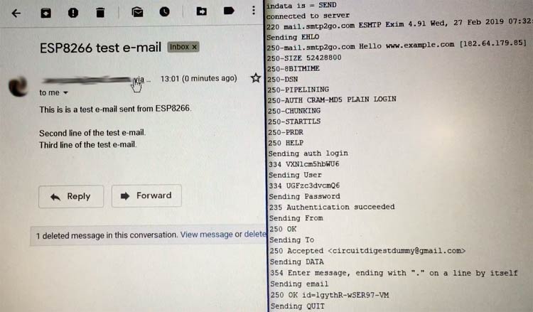
Client.println(F("Subject: ESP8266 test e-mail\r\n"));
Client.println(F("This is is a test e-mail sent from ESP8266.\n"));
Client.println(F("Second line of the test e-mail."));
Client.println(F("Third line of the test e-mail."));
//
Client.println(F("."));
if (!emailResp())
return 0;
//
Serial.println(F("Sending QUIT"));
Client.println(F("QUIT"));
if (!emailResp())
return 0;
//
Client.stop();
Serial.println(F("disconnected"));
return 1;
}
byte emailResp()
{
byte responseCode;
byte readByte;
int loopCount = 0;
while (!Client.available())
{
delay(1);
loopCount++;
// Wait for 20 seconds and if nothing is received, stop.
if (loopCount > 20000)
{
Client.stop();
Serial.println(F("\r\nTimeout"));
return 0;
}
}
responseCode = Client.peek();
while (Client.available())
{
readByte = Client.read();
Serial.write(readByte);
}
if (responseCode >= '4')
{
// efail();
return 0;
}
return 1;
}
Atmega16 Code
#define F_CPU 16000000UL // define cpu frquency
#include<avr/io.h>
#include<util/delay.h>
#include <stdlib.h>
#include <stdio.h>
#define BAUD_PRESCALE (((F_CPU / (USART_BAUDRATE * 16UL))) - 1) // convert to baudrate dec value
void UART_init(long USART_BAUDRATE)
{
UCSRB |= (1 << RXEN) | (1 << TXEN); // Turn on transmission and reception by setting RX Tx bits
UCSRC |= (1 << URSEL) | (1 << UCSZ0) | (1 << UCSZ1); // Use 8-bit character sizes
UBRRL = BAUD_PRESCALE; // Load lower 8-bits of the baud rate value
UBRRH = (BAUD_PRESCALE >> 8); // Load upper 8-bits of the baud rate value
}
void UART_TxChar(char c)
{
while (! (UCSRA & (1<<UDRE))); // Wait for empty transmit buffer
UDR = c;
}
void UART_sendString(char *str)
{
unsigned char s=0;
while (str[s]!=0) // string till null
{
UART_TxChar(str[s]); // send s to UART_TxChar(s) function
s++;
}
}
int main(void)
{
UART_init(9600); // initialise UART communication
UART_sendString("TEST");
//DDR Data Direction Register
DDRA |= (1<<0); //Setting pin0 of PORTA for output mode -led
DDRA &= ~(1<<1); //Setting pin1 of PORTA for input mode -push button
PORTA |= (1<<1); //Giving a high value to pin 1
while(1)
{
if(bit_is_clear(PINA,1)) //if push button is not pressed
{
PORTA |= (1<<0); // turn on led
_delay_ms(20);
}
else
{ // if pressed then transmit "SEND" command over serial
PORTA &= ~(1<<0); //turn off led
_delay_ms(50);
UART_sendString("SEND"); // send string
_delay_ms(1200);
}
}
}

Hello,
I want atmega32 interface esp8266 and control my circuit through mobile application.