

Humans and machines interact and communicate with one other in many possible ways, computers have monitor, keyboard and mouse, while smart phones have touch screen, gesture control etc and even AR and VR is on its way. But the most basic tool used by humans to communicate is vocal communication, we have the capability to listen and speak and if the machines could somehow do the same then communicating with them could not get any simpler.
Smart watches and smart speakers like Google home, Amazon Echo etc slowly finding its way into our homes and speaking with machines is slowly becoming a reality. So in this tutorial we will learn how we can use the Google assistant which can be invoked from your Smartphone, or Google home or smart watch to control the lights/fans by simply using a voice command. It is not that we are super lazy to toggle loads with switches, but at the end of the day it is the sheer joy of getting things done just with our voice commands. So let’s get started.
Google Assistant controlled Home Automation Project Overview
I am using an Arduino UNO for the microcontroller side and an ESP8266 module for connecting to the internet. Honestly, there are tons of other ways to get this through; you can use more powerful processors like Raspberry Pi or other SOC with in-built Wi-Fi like the ESP12E or ESP32. But I decided to go with the old school Arduino and ESP8266 board to keep the cost down and not to over engineer anything.
For this project, we will also build an Arduino WiFi shield using the ESP8266 which sits snug on top of the Arduino UNO board. This shield can be used to program the ESP8266 using AT command or directly using the Arduino IDE. It also has the option to connect a FTDI module directly to ESP8226 which allows the ESP8266 to be programmed as a stand one device without Arduino and also to flash a new firmware into the ESP8266 module if required. So the shield can be used for many other creative Arduino projects which require internet connection.
To communicate with the Google assistant on our mobile phone we have used the IFTTT services, which configure the assistant to listen for a particular command and trigger a link if the command is received. Now, as you might already know the ESP8266 can read information from the internet only through API calls, so we need a platform which can provide us this API option this is where ThingSpeak comes in. Basically the voice command given to Google assistant changes the value of a field in our ThingSpeak channel accordingly. While the ESP8266 periodically checks the value of this field using API calls and sends this value to Arduino using serial communication. The Arduino then performs required action like toggling a relay based on the value received.
Arduino Uno Wi-Fi Shield using ESP8266
Let us start by interfacing the Arduino UNO board with the ESP8266 Wi-Fi module. The ESP8266 is a tricky module to use; it needs its own power source and a specific connection set-up to communicate with Arduino. If you are an absolute beginner then it is highly recommended to read the Getting started with ESP8266 tutorial before proceeding any further.
Do remember that the ESP8266 when purchased comes with a default firmware which is capable of communicating with AT commands. But if the module has been directly programmed with Arduino, then the default firmware will be erased and it has to be flashed again if AT commands are to be used. Details on how to use flash will be explained later. The circuit diagram for the Wi-Fi shield is shown below

We have used an LM317 as a 3.3V voltage regulator. This 3.3V is used to power the ESP8266 module because the 3.3V from Arduino UNO will not be able to source enough current for the ESP module. The LM317 input pin can be powered by the DC input barrel jack of the Vin pin of the Arduino UNO board.
The GPIO0 pin of the ESP module is connected to a jumper pin which can be toggled to connect the pin to ground. This allows the user to set the ESP module to work either in AT command mode or Programming mode (Arduino IDE). Both the GPIO0 and GPIO2 is connected to a external connector so that these GPIO pins can also be utilized.
Finally on the Arduino side, we have connected the Rx and Tx pin of the ESP8266 module to the 12 and 13 pin of Arduino. We did not use the hardware serial (pin 0 and 1) to make debugging easy. You can also notice that an option to connect the 16x2 LCD is also provided, so that it can be mounted directly on top of the shield. The LCD is powered by the 5V pin of the Arduino.
Fabricating PCB for ESP8266 Wi-Fi Module using EasyEDA
A challenging part in designing a shield for Arduino boards is getting the footprint right. If the dimensions go wrong then the shield will not fit properly into the Arduino UNO board. But, lucky enough, EasyEDA provides footprint for almost all components in the market. This is because of its vast user community where users create footprint and makes it available for public to use it their projects.
EasyEDA is an online EDA tool which I have previously used many times and found it very convenient to use since it has a good collection of footprints and it is open-source. After designing the PCB, we can order the PCB samples by their low cost PCB fabrication services. They also offer component sourcing service where they have a large stock of electronic components and users can order their required components along with the PCB order.
While designing your circuits and PCBs, you can also make your circuit and PCB designs public so that other users can copy or edit them and can take benefit from your work, we have also made our whole Circuit and PCB layouts public for this circuit, check the below link:
https://easyeda.com/CircuitDigest/Arduino-WiFi-shield
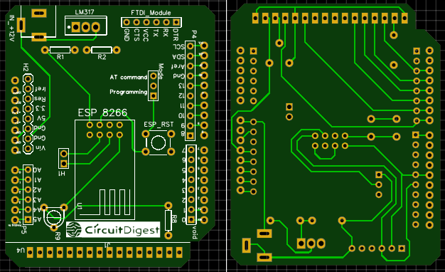
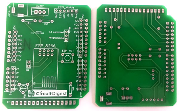
You can view any Layer (Top, Bottom, Topsilk, bottomsilk etc) of the PCB by selecting the layer form the ‘Layers’ Window. Apart from this they also provide a 3D model view of the PCB on how it would appear after fabrication. The snapshot of the top layer and bottom layer of the Wi-Fi shield would appear something like this
Calculating and Ordering PCB Samples online using EasyEDA
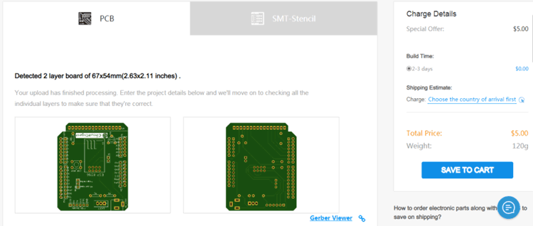
After completing the design of this Arduino Uno Wi-Fi Module, you can order the PCB through JLCPCB.com. To order the PCB from JLCPCB, you need Gerber File. To download Gerber files of your PCB just click the Generate Fabrication File button on EasyEDA editor page, then download the Gerber file from there or you can click on Order at JLCPCB as shown in below image. This will redirect you to JLCPCB.com, where you can select the number of PCBs you want to order, how many copper layers you need, the PCB thickness, copper weight, and even the PCB color, like the snapshot shown below:
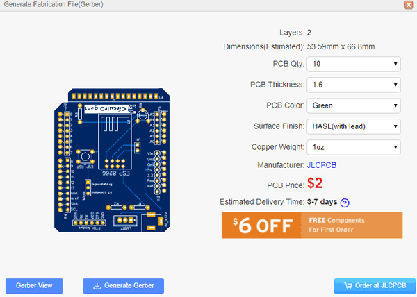
After clicking on order at JLCPCB button, it will take you to JLCPCB website where you can order the PCB in very low rate which is $2. Their build time is also very less which is 48 hours with DHL delivery of 3-5 days, basically you will get your PCBs within a week of ordering.
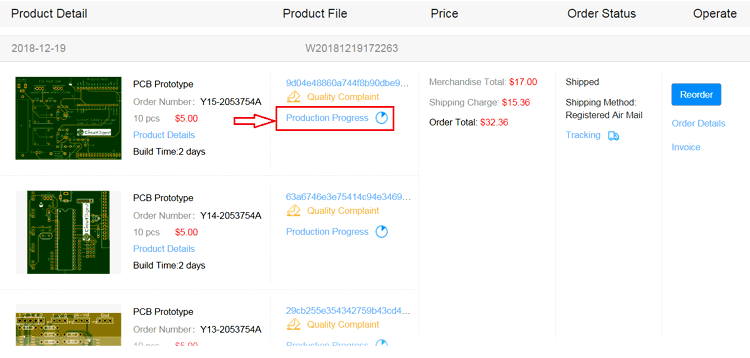
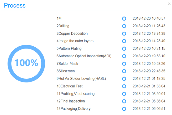
After ordering the PCB, you can check the Production Progress of your PCB with date and time. You can check it by going on Account page and click on "Production Progress" link under the PCB like, shown in below image.
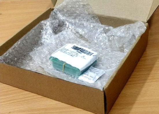
After few days of ordering PCB’s I got the PCB samples in nice packaging as shown in below pictures.
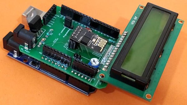
After making sure the tracks and footprints were correct. I proceeded with assembling the PCB, I used female headers to place the Arduino Nano and LCD so that I can remove them later if I need them for other projects. The completely soldered board looks like this below

Arduino Wi-Fi Shield Programming mode and AT mode
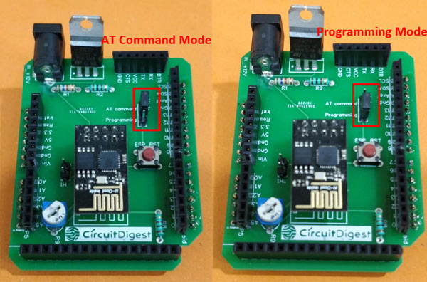
When the ESP8266 is programmed directly using the Arduino IDE or when it is to be flashed, the GPIO 0 pin should be connected to ground and Reset pin has to be momentarily connected to ground every time before the uploading process. Similarly when the ESP8266 is working with AT commands the GPIO pin should be left free and again the Reset pin should be momentarily connected to ground to reset it.
To make things easier the Wi-Fi shield that we designed has a toggle pin which can shift between Programming mode and AT command mode as shown in the below images. Also the Reset pin can be connected to ground by simply pressing the reset button (red color) everytime before uploading the code.
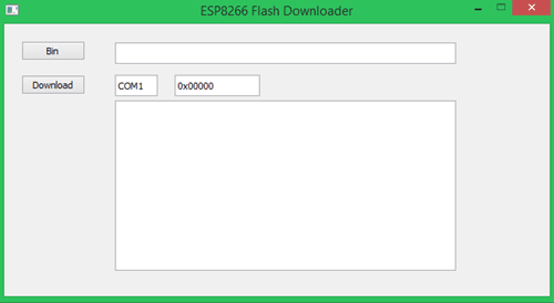
The board also has an option to connect FTDI module to the ESP directly which is useful for flashing the ESP8266 module. To flash it connect the FTDI module and set the pin in programming mode as shown below. Then download the ESP8266_Flasher software and the firmware bin file from the given link. Then open the software and browse for the bin file using Bin button, then type in the right COM port and leave the address to be 0x00000 as default. Finally click on the Download button to flash the ESP8266 module. The software is also shown in the image below, but remember that you have to flash it only if default firmware on ESP8266 is overwritten.
Setting up the ThingSpeak channel for Google Assistant
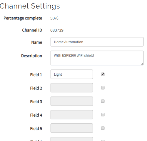
We need a channel in ThingSpeak which will store data from the Google assistant and later allows the same to be retrieved by the ESP8266 using API calls. If you are new to ThingSpeak set up an account by signing up on thingspeak.com and click on new channel, also check our previous project to learn more about using ThingSpeak with Arduino. You can pick any name for your channel and give it a description. Since we are toggling only one light I have used only one field and named it as Light but again you can use as many as you want. My channel settings looks something like this, make note of the Channel ID which is 683739 in my case and field number which is 1 in my case, we will need it in future.
Next click on the API keys tab, here you will be provided with two API keys one for Write function and the other for read function. You can read or write values to the filed only using these keys respectively. Every key will be unique, mine is shown below yours will be different for sure. Never share your keys as it can give permission to write or read to your channel. They keys shown below were destroyed after usage.
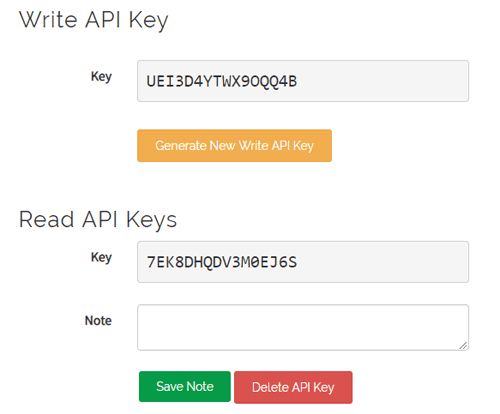
Now let us look at the API GET calls using which we can write and read data to the field that we just created.
Read from Thing Field:
api.thingspeak.com/channels/683739/fields/1/last.json?api_key=7EK8DHQDV3M0EJ6S&results=2
Write to Thing Field:
api.thingspeak.com/update?api_key=UEI3D4YTWX9OQQ4B&field1=7
These are my API you have to replace the key value with your keys and also change the channel ID according to your ThingSpeak channel. If you have selected the first field as shown in the image then the field value need not be changed.
You can also try loading these API calls on your Brower and check how it working. In the above write to thing field we are writing 7 (appended at the last) to the channel. You can load this on your browser and check if the value is being reflected on your ThingSpeak account. Similarly the read from Thing Field API call when loaded in browser should give you the value that you have sent to field previously, in this case 7.
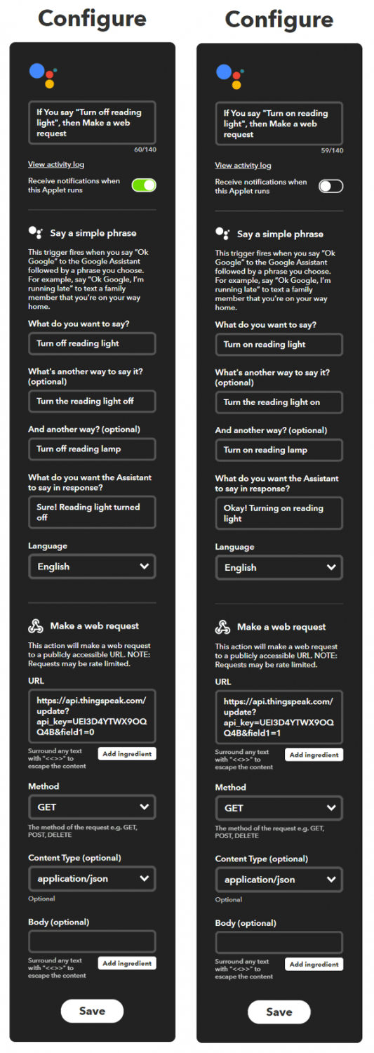
Setting up IFTTT Applets
Now we know how to send and read values form the field, next we have to set two applets in our IFTTT account. If you are new to IFTTT simply sign up for it and link you Gmail account, this Gmail account should be the same one form which you are using the Google voice assistant. Of the two applets both will be used write value to the field using the above discussed link. But, one would listen for “Turn on Reading Light” and write “1” to the field while the other applet will listen for “Turn off Reading Light” and write “0” using the above API calls.
To create an Applet, get into my applets and click on “New Applet”. Then in this “This” section select the Google voice assistant and in the “That” section select the Webhooks service. It is very similar to what we did with our IoT based door security project. If you are confused on how to do it refer this article and the following image will also help you.
Programming the Arduino for Google Assistant Home Automation
Both the IFTTT and the ThingSpeak account should be set by now. So, based on the command given to our Google assistant the IFTTT will send a value (0 or 1) to our ThingSpeak account. Now, on our Arduino side we have to write a program to check if the value of field is 0 or 1. If 0 we have to turn off the light and if 1 we have to turn it on.
The complete program to do the same is given at the end, I am breaking the program into meaningful snippets and explaining them below. We begin by defining the pins to which the ESP and the LCD is connected to Arduino. You can refer the circuit diagram to verify the same.
SoftwareSerial ESP(12,13); //ESP is connected to 12 and 13 pin of Arduino
const int rs = 7, en = 6, d4 = 5, d5 = 4, d6 = 3, d7 = 2; //Mention the pin number for LCD connection
LiquidCrystal lcd(rs, en, d4, d5, d6, d7);
Then we have to feed in few critical parameters, like the name of the Wi-Fi to which the ESP should connect to its password and then finally the API call request that we obtained from our ThingSpeak. Be sure that you have changed these credentials according to your applications. Verify the API key and load it in browser to make sure.
String WiFi_SSID = "Oneplus";
String WiFi_Pass = "nightfury";
String sendData = "GET /channels/683739/fields/1/last.json?api_key=7EK8DHQDV3M0EJ6S&results=2";
String output = ""; //Initialize a null string variable
Inside the setup function, we declare pin 10 as output this is where we connect our load thorough a relay. Then we display a small intro text on the LCD and initialize serial monitor using the below lines of code.
  pinMode(10,OUTPUT);
  lcd.begin(16, 2); //Initialise 16*2 LCD
  lcd.print("  Arduino WiFi"); //Intro Message line 1
  lcd.setCursor(0, 1);
  lcd.print("    Shield    "); //Intro Message line 2
  delay(2000);
  Serial.begin (9600);
By default the ESP works with a baud rate of 115200, but the Arduino is not fast enough to read data from the ESP at such high speed. It does read data but I personally found a lot of garbage values many a time. Hence I decided to change the ESP to work with 9600 baud rate using the AT+CIOBAUD=9600 as shown below. After changing the baud rate we can re-initialize the software serial to work with 9600 baud rate.
  ESP.begin(115200);
  ESP.println("AT+CIOBAUD=9600");
  delay(100);
  ESP.begin(9600);
Next, we have a series of AT commands that has to be sent to the module only once. They include turning off the Echo option (ATE0) then setting the ESP to work in station mode (AT+CWMODE=1) and then connecting it to the router using (AT+CWJAP) etc. Once it is executed the ESP will remember these details and will connect to our Router as a station every time we power it on. So you can comment these lines after first time usage (optional though).
ESP_talk("ATE0", 1000); //Turn off Echo
ESP_talk("AT+CWMODE=1", 1000); //Set ESP as station
ESP_talk("AT+CWJAP=\""+ WiFi_SSID +"\",\""+ WiFi_Pass +"\"", 5000); //Connect to WiFi
delay(1000);
ESP_talk("AT+CIPMUX=1",1000);
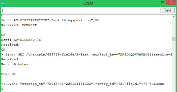
delay(1000);Inside the main loop function, we have to connect to our ThingSpeak API. This can be done by first starting a TCP connection to the ThingSpeak network by the following command.
ESP_talk("AT+CIPSTART=\"TCP\",\"api.thingspeak.com\",80",1000);Then we have to tell how many characters are being sent to the connection using the AT+CIPSEND. In my case it is 76. Because the below command that we will send, we have 74 characters and with that we have to add 2 for “/n” which gives 76.
GET /channels/683739/fields/1/last.json?api_key=7EK8DHQDV3M0EJ6S&results=2
Then we actually send the above data which is stored in the variable sendData. These commands are sent with a delay of 100ms for stability but it is not mandatory. The program for the same is shown below.
   ESP_talk("AT+CIPSTART=\"TCP\",\"api.thingspeak.com\",80",1000); //AT+CIPSTART="TCP","api.thingspeak.com",80
    delay(100);
    ESP_talk("AT+CIPSEND=76",1000);
    delay(100);
    ESP_talk(sendData,1000);
    delay(100);
The above code will fetch the field data as a string value from the ThingSpeak website and store it in the variable “output” which will look something like this.
+IPD,64:{"created_at":"2019-01-22T12:13:32Z","entry_id":15,"field1":"0"}CLOSEDAs you can see, off the entire string value, we only need to check if the field1 value is 0 or 1. So we use the charAT function in Arduino to fetch that particular char value form the entire string. The location of the value is 11 steps behind from the last value. So the code looks like
int light_value = int (output.charAt(output.length()-11))-48;
The last step is to compare this value with 0 and 1. Then toggle the light on if it is a 1 and turn it off if it is a 0. The LCD is also made to display the result, based on the field value.
   lcd.clear();
    lcd.print("Listning...."); //Intro Message line 1
    lcd.setCursor(0, 1);
    if (light_value == 0) //light should be off
    {
      lcd.print("Light is OFF :-(" );
      digitalWrite(10,LOW);
    }
    if (light_value == 1) //light should be off
    {
     lcd.print(":-) Light is ON");
      digitalWrite(10,HIGH);
    }
You would have noticed the ESP_talk function being used extensively throughout the program. This function basically has two parameters one is the actual command which is sent to the ESP module and other is the time out value within which the ESP should respond back for the sent command. The response from the ESP is then stored in the variable output. This comes in very handy when debugging the ESP module. The function definition is shown below.
 void ESP_talk(String AT_cmd, const int timeout)
{
  Serial.print("Sent: ");
  Serial.print(AT_cmd);
  ESP.println(AT_cmd); //print to ESP through software serial
  Serial.println("");//Move to next line

  long int time = millis();

  output=""; //clear the string

  while ( (time + timeout) > millis())
  {
    while (ESP.available())
    {
      char i = ESP.read(); // read one char
      output += i; //Combine char to string
    }
  }

  Serial.print("Received: ");
  Serial.print(output);
}
Using Google Assistant to Toggle Lights
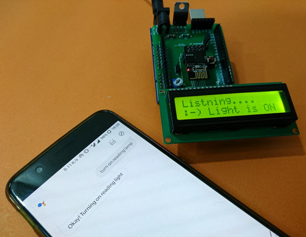
So we are all set to use our Arduino ESP8266 Wi-Fi module to control the Home Appliances from anywhere using Google Assistant.
As explained the above program is used to toggle the pin 10. So you can add a relay to the pin 10 and connect any AC load within relay rating as required. My setup with the Relay and the Arduino board with Wi-Fi shield is shown below.
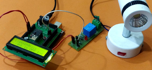
I have used a small reading lamp as a demo load but you can use anything of your choice. Power up the set-up and speak out the command to your Google assistant and you should see the Light getting controlled accordingly. You can also see the ThingSpeak channel values getting changed as you issue command to your Google assistant. For debugging you can open your Serial monitor to check if everything is working fine. If yes your serial monitor should display something like this.
You can watch the video below to check the complete working of the project and also check our other Arduino Home Automation Projects.
Hope you liked the project and enjoyed building it. If you have any problem please feel free to leave them in the comment section below and I will try my best to address it. You can also use the forums for other technical questions.
Complete Project Code
/*Home automation using Google assistant and thingspeak using Arduino Shield
 *Shield details:  https://easyeda.com/CircuitDigest/Arduino-WiFi-shield
 *Author: B.Aswinth Raj
 *Dated: 21-1-2019
 */
//Use the new flah tool ad bin file to get the latest firmware and then use AT+CIOBAUD=9600 to change the baud, // AT+UART_DEF=9600,8,1,0,0 (for old firmware)

#include <LiquidCrystal.h> //Librarey for LCD display
#include <SoftwareSerial.h> //Librarey for serial connection with ESP
SoftwareSerial ESP(12,13); //ESP is connected to 12 and 13 pin of Arduino
const int rs = 7, en = 6, d4 = 5, d5 = 4, d6 = 3, d7 = 2; //Mention the pin number for LCD connection
LiquidCrystal lcd(rs, en, d4, d5, d6, d7);

String WiFi_SSID = "Oneplus";
String WiFi_Pass = "nightfury";
String sendData = "GET /channels/683739/fields/1/last.json?api_key=7EK8DHQDV3M0EJ6S&results=2";
String output = ""; //Initialize a null string variable

void setup() {
  pinMode(10,OUTPUT);

  lcd.begin(16, 2); //Initialise 16*2 LCD
  lcd.print("  Arduino WiFi"); //Intro Message line 1
  lcd.setCursor(0, 1);
  lcd.print("    Shield    "); //Intro Message line 2
  delay(2000);
  Serial.begin (9600);

  ESP.begin(115200);
  ESP.println("AT+CIOBAUD=9600");
  delay(100);
  ESP.begin(9600);


   ESP_talk("ATE0", 1000); //Turn off Echo
  /*ESP_talk("AT+CWMODE=1", 1000); //Set ESP as station
   ESP_talk("AT+CWJAP=\""+ WiFi_SSID +"\",\""+ WiFi_Pass +"\"", 5000); //Connect to WiFi
   delay(1000);
   ESP_talk("AT+CIPMUX=1",1000);
   delay(1000); */
}

void loop() {

    ESP_talk("AT+CIPSTART=\"TCP\",\"api.thingspeak.com\",80",1000); //AT+CIPSTART="TCP","api.thingspeak.com",80
    delay(100);
    ESP_talk("AT+CIPSEND=76",1000);
    delay(100);
    ESP_talk(sendData,1000);
    delay(100);
    int light_value = int (output.charAt(output.length()-11))-48; //read the required value form string and convert it to int
    Serial.println(light_value);
    lcd.clear();
    lcd.print("Listning...."); //Intro Message line 1
    lcd.setCursor(0, 1);
    if (light_value == 0) //light should be off
    {
      lcd.print("Light is OFF :-(" );
      digitalWrite(10,LOW);
    }
    if (light_value == 1) //light should be off
    {
      lcd.print(":-) Light is ON");
      digitalWrite(10,HIGH);
    }

    delay(500);
}

void ESP_talk(String AT_cmd, const int timeout)
{
  Serial.print("Sent: ");
  Serial.print(AT_cmd);
  ESP.println(AT_cmd); //print to ESP through software serial
  Serial.println("");//Move to next line


  long int time = millis();
  output=""; //clear the string

  while ( (time + timeout) > millis())
  {
    while (ESP.available())
    {
      char i = ESP.read(); // read one char
      output += i; //Combine char to string
    }
  }

  Serial.print("Received: ");
  Serial.print(output);
}
Comments
The link provided to download the Flasher and Bin file for the ESP8266, it's not available. Any idea where can I found it?
Thank you,
Rod.
Hi Aisha:
What they explain on "Step 1"..... that is exactly the files to update the new firmware requiered for this particular project?
Thank you,
Rod.
Is the adapter board (PCB designed on the example where the ESP 8266 & FDTI Module are hook up) compatible pin to pin with the Arduino Mega? It look that is possible in order to approach the project with an Arduino Mega..
Thank you,
Rod.
i tried this but am getting a different thing from the serial monitor. here is the code and the screenshot of the serial monitor attached.
/*Home automation using Google assistant and thingspeak using Arduino Shield
*Shield details: https://easyeda.com/CircuitDigest/Arduino-WiFi-shield
*Author: B.Aswinth Raj
*Website: www.circuitdigest.com
*Dated: 21-1-2019
*/
//Use the new flah tool ad bin file to get the latest firmware and then use AT+CIOBAUD=9600 to change the baud, // AT+UART_DEF=9600,8,1,0,0 (for old firmware)
#include <LiquidCrystal.h> //Librarey for LCD display
#include <SoftwareSerial.h> //Librarey for serial connection with ESP
SoftwareSerial ESP(12,13); //ESP is connected to 12 and 13 pin of Arduino
const int rs = 7, en = 6, d4 = 5, d5 = 4, d6 = 3, d7 = 2; //Mention the pin number for LCD connection
LiquidCrystal lcd(rs, en, d4, d5, d6, d7);
String WiFi_SSID = "PRINZLITE";
String WiFi_Pass = "Prince2k7";
String sendData = "GET /channels/731547/fields/1/last.json?api_key=HRR67Q436VSY6S7F&results=2";
String output = ""; //Initialize a null string variable
void setup() {
pinMode(10,OUTPUT);
lcd.begin(16, 2); //Initialise 16*2 LCD
lcd.print(" Arduino WiFi"); //Intro Message line 1
lcd.setCursor(0, 1);
lcd.print(" Shield "); //Intro Message line 2
delay(2000);
Serial.begin (9600);
ESP.begin(115200);
ESP.println("AT+CIOBAUD=9600");
delay(100);
ESP.begin(9600);
ESP_talk("ATE0", 1000); //Turn off Echo
/*ESP_talk("AT+CWMODE=1", 1000); //Set ESP as station
ESP_talk("AT+CWJAP=\""+ WiFi_SSID +"\",\""+ WiFi_Pass +"\"", 5000); //Connect to WiFi
delay(1000);
ESP_talk("AT+CIPMUX=1",1000);
delay(1000); */
}
void loop() {
ESP_talk("AT+CIPSTART=\"TCP\",\"api.thingspeak.com\",80",1000); //AT+CIPSTART="TCP","api.thingspeak.com",80
delay(100);
ESP_talk("AT+CIPSEND=76",1000);
delay(100);
ESP_talk(sendData,1000);
delay(100);
int light_value = int (output.charAt(output.length()-11))-48; //read the required value form string and convert it to int
Serial.println(light_value);
lcd.clear();
lcd.print("Listning...."); //Intro Message line 1
lcd.setCursor(0, 1);
if (light_value == 0) //light should be off
{
lcd.print("Light is OFF :-(" );
digitalWrite(10,LOW);
}
if (light_value == 1) //light should be off
{
lcd.print(":-) Light is ON");
digitalWrite(10,HIGH);
}
delay(500);
}
void ESP_talk(String AT_cmd, const int timeout)
{
Serial.print("Sent: ");
Serial.print(AT_cmd);
ESP.println(AT_cmd); //print to ESP through software serial
Serial.println("");//Move to next line
long int time = millis();
output=""; //clear the string
while ( (time + timeout) > millis())
{
while (ESP.available())
{
char i = ESP.read(); // read one char
output += i; //Combine char to string
}
}
Serial.print("Received: ");
Serial.print(output);
}
I will need the screenshot of the serial monitor to look into your erroe. also it is better to use the forums for these questions
Hi, thanks for this great tutorial. My problem with the project is that I have different message displayed on my serial monitor and the LED attached to D10 of Arduino is not responding despite the Thingspeak is working when i give command to google assistant. Please what could be the possible error. Thanks.

It is not getting the field value ...
Comment pls