

This is another interesting IOT project in which we will build a Security system which can trigger an E-mail when it detects someone. This project has blend in the power of ESP8266, PIR sensor and ISD1820 Voice module. At the end of this article you would have built a fully functional Security system which can be Armed/Disarmed (Activated/De-activated) remotely via internet. You can record your own audio clip which will be played when a movement is detected and also send a mail with Date and time to a particular E-mail ID stating the intrusion. Cool enough.....!!!??
So let us build it..
Materials Required:
The materials required to build this project is listed below
- ESP8266
- PIR sensor
- ISD1820 Voice Module
- LM317,LM7805
- BC547 (2Nos)
- 1K, 200ohm,330ohm resistors
- 10uf and 0.1uf Capacitors
- 12V adapter / 9V battery to power the setup
Modules Explanation:
The project houses three important components which are the ESP8266 module, PIR sensor and ISD1820 Voice module. If you are familiar with these modules then you can skip this part on move on to the schematics but if you want to know how they work read on.
ESP8266 Module:
I am sure you would have come across this module some time or other. It is a very famous and powerful WiFi module which is mostly used in IOT projects.
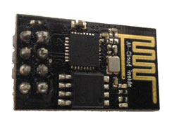

This project assumes that you know how to program an ESP8266 module if not kindly visit the below two tutorials where I have explained you how to get started with ESP8266 and how you can program one using the Arduino IDE. You have to know this to complete the project.
PIR sensor:
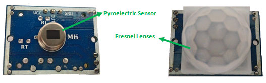
The PIR sensor stands for Passive Infrared sensor. It is a low cost sensor which can detect the presence of Human beings or animals. There are two important materials present in the sensor one is the pyroelectric crystal which can detect the heat signatures from a living organism (humans/animals) and the other is a Fresnel lenses which can widen the range of the sensor. Also the PIR sensor modules provide us some options to adjust the working of the sensor as shown in below image.
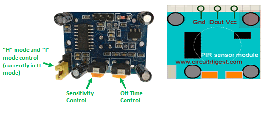
The two potentiometers (orange colour) are used to control the sensitivity and trigger on time of the sensor. Basically the Dout pin of the sensor is present in between the Vcc and Gnd pins. The module works on 3.3V but can be powered with 5V as well. On the top left corner it also has a trigger pin setup which can be used to make the module work in two different modes. One is the “H” mode and the other is the “I” mode.
In “H” mode the output pin Dout will go high (3.3V) when a person is detected within range and goes low after a particular time (time is set by potentiometer). In this mode the output pin will go high irrespective of whether the person is still present inside the range or has left the area. We are using our module in “H” mode in our project.
In “I” mode the output pin Dout will go high (3.3V) when a person is detected within range and will stay high as long as he/she stays within the limit of the Sensors range. Once the person has left the area the pin will go low after the particular time which can be set using the potentiometer.
Note: The position of potentiometers or pins may vary based on your PIR sensor vendor. Follow the Silk screen to determine you pinouts
ISD1820 Voice module:
The ISD 1820 Voice module is really a cool module that could spice up your Projects with Voice announcements. This module is capable of recording an Audio clip for 10 seconds and then playing it when required. The module itself comes with a microphone and a speaker (8ohms 0.5watts) and it should look something like this shown below.
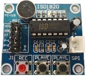
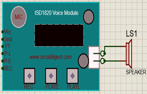
The module works on +5V and can powered using the berg sticks on the left. It also has three buttons at the bottom which are Rec. button, PlayE. button and PlayL. button respectively. You can record your voice by pressing the Rec. button and play it using the PlayE button. The PlayL will play the voice as long as you hold the button. When interfacing with a MCU or ESP we can use the pins on the left. These pins are 3V-5V tolerable and hence can be directly driven by Arduino/ESP8266. In our project we are controlling the PLAYE pin using the GPIO 0 pin of our ESP8266 module. So that we can play the recorded voice when an intruder is detected.
Schematic and Hardware
The complete schematic of this IoT security system project is shown below:

The circuit consists of two voltage Regulators. One is a 3.3V regulator designed using the LM317 and the other is a 5V regulator done using the 7805 Regulator IC. LM317 is a variable voltage regulator whose output is set to 3.3V by using the resistors 200ohm and 330ohm. Both the regulators are powered by using a 12V adapter. The power consumption of this circuit is very minimal hence a 9V battery can also be used in place of a 12V adapter.
The PIR sensor and Voice module is turned on by making the GPIO 2 pin high. This pin will drive the BC547 through a 1k current limiting resistor and complete the power circuit for both the modules. The pin GPIO_0 is used an Input pin. It is connected to the Dout pin of PIR sensor thorough a BC547 transistor. When this pin goes high we will trigger an E-mail stating the intrusion through our Arduino Program.
The source current of the output pins (Dout,GPIO_2 and GPIO2) are vey less hence I have used a transistor to drive them. Also the GPIO pins of the ESP8266 must not be loaded when the module is powered on else the module will enter in to infinite reset loop. TO avoid this I have placed two switches to temporarily disconnect them while powering up.
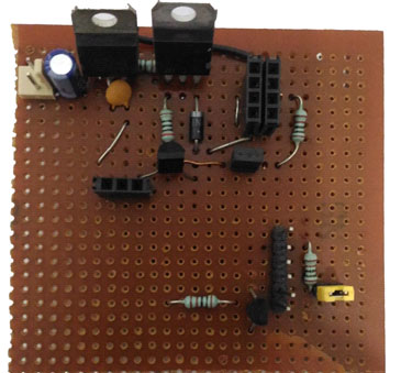
You can solder the above circuits to a Perf board or simply use a breadboard. I have used female/male berg sticks so that I can avoid soldering on the modules. Once done your board should look something like below
Creating an API to send E-mail using IFTTT:
Once the hardware is ready lets create an API (Application Program Interface) that can send E-mail to a particular E-mail ID. This can be easily done with the help of a website called IFTTT.com. I have also covered a project that could send SMS using ESP8266 and Email using PIC Microcontroller which uses the same IFTTT services.
If you have not yet used IFTTT visit the video at the end of this tutorial, if you are familiar simply follow the below steps
1. Log In into your IFTTT account
2. Search for “Maker Web hooks” and click on connect
3. Now search for “Gmail” and click on connect and follow the steps to give access
4. Then, create an Applet by clicking on My Applet-> New Applet.
5. Here, the “This” function will be for web makerhooks service and “that” function will be Gmail Services
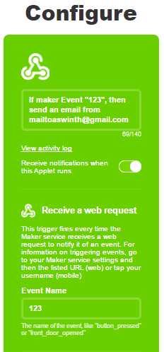
6. So click on “This”, search and select Web maker hooks. It will ask for event name i have named my event as “123” you can name yours anything
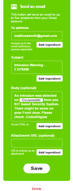
7. Then click on “That”, search and select Gmail and enter the subject and body of the mail.
8. Once all the required details are entered your Apple should be ready and it should look something like this below
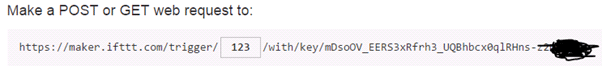
9. Now, search and get into Web Maker Hooks again and click on “Documentation”. Then under event name enter the event name we used in the Applet. In my case it is “123” and copy the URL since we will be needing it in our Arduino program. The URL should like something like this below.
10.You can click on “Test it” button to check if you link is working properly and you should have got a test mail by doing so.
Arduino Program
The Arduino Program for this project is simple and easy. We have to simply make the ESP act as a AP and STA. Then create a webpage by using HTML code where we can ARM/DISARM the Alarm system. The complete code is given at the end of this tutorial the code is also explained using comment lines. Further the important lines are explained below.
const char* ssid = "BPAS home";  //Enter you Wifi SSID here

const char* password = "cracksen"; //Enter your password here
In the above line of code change the SSID name and Password to your routers SSID name and its corresponding password.
If you want to find at which IP your ESP8266 is connected to you can find it out by opening the serial monitor the following lines of code will print your IP on Arduino IDE serial monitor.
Serial.println("");

  Serial.print("Connected to ");

  Serial.println(ssid);

  Serial.print("IP address: ");

  Serial.println(WiFi.localIP()); //Serial monitor will give the IP addrss of your ESP module
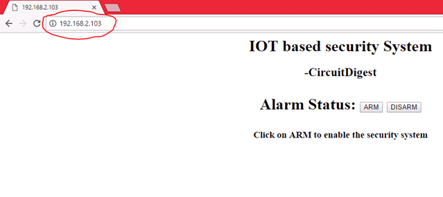
The HTML code which is responsible for creating a webpage is given below. You can customize you webpage with your own code. I have modified the feedback part to acknowledge the user if the page was loaded successfully.
//HTML code for webpage// mainPage += "<h1 align=\"center\">IOT based security System</h1><h2 align=\"center\">-CircuitDigest</h2><h1 align=\"center\"><p>Alarm Status: <a href=\"switch2On\"><button>ARM</button></a> <a href=\"switch2Off\"><button>DISARM</button> </a></p>"; feedback = "<h3 align=\"center\">Click on ARM to enable the security system</h3>"; //End of HTML code//
The below lines of code determines what should be done when the Alarm is Armed or Disarmed. In my program I have changed the feedback part of the HTML code and Made the GPIO 2 pin HIGH/LOW based on the button as shown below
  server.on("/switch2On", [](){

    feedback = "<h3 align=\"center\">Alarm is up and running </h3>"; //HTML code modification

    currentPage=mainPage+feedback;

    server.send(200, "text/html", currentPage);

    currentPage="";

    digitalWrite(GPIO_2, HIGH); //Turn on PIR and Voice module

    power_module=true;

    delay(1000);

  });

  server.on("/switch2Off", [](){

    feedback = "<h3 align=\"center\">Alarm is down</h3>"; //HTML code modification

    currentPage=mainPage+feedback;

    server.send(200, "text/html", currentPage);

    currentPage="";

    digitalWrite(GPIO_2, LOW); //Turn off PIT and Voice Module

    power_module=false;

    delay(1000);

  });
Another Important line that must be changed for the system to work properly is the URL string line. You paste the line(after”/trigger”) that you copied from the IFTTT website here. I have shown mine below but do not use my API key use your own here
String url = "/trigger/123/with/key/mDsoOV_EERS3xRfrh3_UQBhbcx0qlRHns-z2qXXXXX"; //Must change it to your API URL
The rest of the code is self explanatory, if you have any doubt you can use the comment section and I will help you out.

Working
Once you are ready with the Hardware and the codes you can upload the program to your ESP8266 module by using a FTDI board. IF you are not sure how to upload programs to ESP8266 using Arduino IDE visit this tutorial.
After uploading the program click on serial monitor and you should see something like this below. If not reset your ESP8266 module and try again
.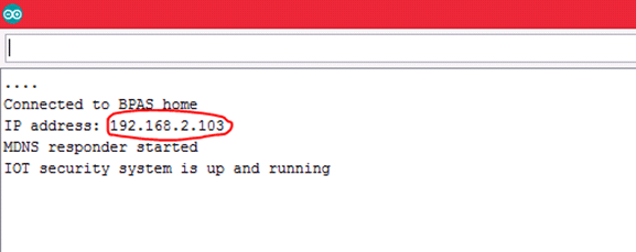
Here, you can also note down the IP address that is allocated to your ESP8266 module. Then you can use the IP to load up the webpage on your Browser and Arm/Disarm your IoT Security system from there as shown in the below picture.
Once you have verified all these you can now transfer your ESP8266 to the Perf board and power it ON and then short the switches as shown in the Video.
After powering on you can use the IP to get into the above shown webpage and enable the Securtiy system. After enabling wait for 50-60 seconds for the PIR sensor to calibrate.
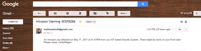
Now you project is ready for action, you can leave it in a place you wish and if anyone crosses that places and falls within the range of PIR sensor a voice message will be triggered and an E-mail wil be sent to your E-mail ID with the Date and time he/she crossed. The E-mail is shown below.
So, that is it.. I hope you liked the project and will enjoy making your own. The complete working of the Project is shown in the Video below. If you have any doubts or suggestions you can write them on the comment section below and I will respond as much as possible.
Complete Project Code
/*Program for : IOT based Security system system with Voice warning
* Program by :Aswinth Raj
* Published on : circuitdigest.com
* Dated:17-05-2017
*/
#include <ESP8266WiFi.h>
#include <WiFiClient.h>
#include <WiFiClientSecure.h>
#include <ESP8266WebServer.h>
#include <ESP8266mDNS.h>
MDNSResponder mdns;
boolean trigger_sms = false;
boolean power_module = false;
const char* ssid = "BPAS home"; //Enter you Wifi SSID here
const char* password = "cracksen"; //Enter your password here
ESP8266WebServer server(80);
String mainPage = ""; //The default page
String feedback = ""; //Gives staus of the switch
String currentPage = ""; //Combines main and feedback page
int GPIO_0 = 0; //Pin defanition
int GPIO_2 = 2; //Pin defanition
void setup(void){
//HTML code for webpage//
mainPage += "<h1 align=\"center\">IOT based security System</h1><h2 align=\"center\">-CircuitDigest</h2><h1 align=\"center\"><p>Alarm Status: <a href=\"switch2On\"><button>ARM</button></a> <a href=\"switch2Off\"><button>DISARM</button> </a></p>";
feedback = "<h3 align=\"center\">Click on ARM to enable the security system</h3>";
//End of HTML code//
currentPage = mainPage+feedback;
// preparing GPIOs
pinMode(GPIO_0, INPUT); //feeded by PIR sensor
pinMode(GPIO_2, OUTPUT); //used to turn on PIR and Voice module
digitalWrite(GPIO_2, LOW);
delay(1000);
Serial.begin(115200);
WiFi.begin(ssid, password);
Serial.println("");
// Wait for connection
while (WiFi.status() != WL_CONNECTED) {
delay(500);
Serial.print(".");
}
// config static IP
Serial.println("");
Serial.print("Connected to ");
Serial.println(ssid);
Serial.print("IP address: ");
Serial.println(WiFi.localIP()); //Serial monitor will give the IP addrss of your ESP module
if (mdns.begin("esp8266", WiFi.localIP())) {
Serial.println("MDNS responder started");
}
server.on("/", [](){
currentPage = mainPage+feedback;
server.send(200, "text/html", currentPage);
currentPage = "";
});
server.on("/switch2On", [](){
feedback = "<h3 align=\"center\">Alarm is up and running </h3>"; //HTML code modification
currentPage=mainPage+feedback;
server.send(200, "text/html", currentPage);
currentPage="";
digitalWrite(GPIO_2, HIGH); //Turn on PIR and Voice module
power_module=true;
delay(1000);
});
server.on("/switch2Off", [](){
feedback = "<h3 align=\"center\">Alarm is down</h3>"; //HTML code modification
currentPage=mainPage+feedback;
server.send(200, "text/html", currentPage);
currentPage="";
digitalWrite(GPIO_2, LOW); //Turn off PIT and Voice Module
power_module=false;
delay(1000);
});
server.begin();
Serial.println("IOT security system is up and running");
}
//Function to send an E-mail//
void send_Email()
{
const char* host = "maker.ifttt.com"; //The host of API URL will be the same for all
const int httpsPort = 443;
WiFiClientSecure client;
Serial.print("connecting to ");
Serial.println(host);
if (!client.connect(host, httpsPort)) {
Serial.println("connection failed");
return;
}
String url = "/trigger/123/with/key/mDsoOV_EERS3xRfrh3_UQBhbcx0qlRHns-z2qXXXXX"; //Must change it to your API URL
Serial.print("requesting URL: ");
Serial.println(url);
client.print(String("GET ") + url + " HTTP/1.1\r\n" +
"Host: " + host + "\r\n" +
"User-Agent: BuildFailureDetectorESP8266\r\n" +
"Connection: close\r\n\r\n");
Serial.println("request sent");
while (client.connected()) {
String line = client.readStringUntil('\n');
if (line == "\r") {
Serial.println("headers received");
break;
}
}
String line = client.readStringUntil('\n');
Serial.println("reply was:");
Serial.println("==========");
Serial.println(line);
Serial.println("==========");
Serial.println("closing connection");
}
//Function to send an E-mail
void loop(void){
server.handleClient();
if (digitalRead(GPIO_0==HIGH) && power_module==true)
trigger_sms=true;
else
trigger_sms=false;
if (trigger_sms==true)
{
send_Email(); //If the PIR module is powered and if a person is detected send a E-mail
trigger_sms=false;
delay(2000);
}
}
Comments
If you can afford a WIFI
If you can afford a WIFI board then YES it is possible. But, there will be huge change in code, the concept will remain the same
Sending email to multiple recipients
Hi dear,
Can I use Webhooks instead of the Maker Webhooks which is no longer available.
Secondly I want to send intrusion email to multiple recipients as suggested in your video for this project, but on IFTTT I don't see any option for multiple email addresses.
Can you please guide me to get this project up and running for multiple email addresses.
Thanks & regards
Yawar Saeed
Not receiving any mail
I created app using g mail with webhook but am not receiving any mail for event even I tested, it shows that you have fired but no mail , pl rply
Programming Language
Hey
Hope you are good man. I have some questions.
What is this language?
What is it name?
How can I learn it?
BTW nice work
You should learn about
You should learn about Arduino IDE and ESP8266
The language is C++
Hi, I am not being able to
Hi, I am not being able to establish connection from maker.ifttt.com and i have used the same code as provided above and hence not being able to get mail notification. Please help.
Thanks
ESM8266 Alarm, Security
Hi, I am not being able to establish connection from maker.ifttt.com and i have used the same code as provided above and hence not being able to get mail notification. Please help.
GRIO_0 does not respond to a high level (to an alarm contact)! In the Arm mode, he writes in the port: connecting to maker.ifttt.com.
connection failed
connecting to maker.ifttt.com.
connection failed
Apparently does not want to connect the site maker.ifttt.com.!

Im doing this with an arduino uno wifi board. is that okay. how would the model change. can you please help?