

The MPU6050 is an IC 3-axis accelerometer and a 3-axis gyroscope combined into one unit. It also houses a temperature sensor and a DCM to perform a complex task. The MPU6050 is commonly used in building Drone and other remote robots like a self-balancing robot. In this project we will learn how to use the MPU6050 is built an Inclinometer or Spirit Leveller. As we know an inclinometer is used to check if a surface is perfectly leveled or not, they are available either as sprit bubble ones or as digital meters. In this project, we are going to build a Digital Inclinometer which can be monitored using an Android application. The reason for using a remote display like a mobile phone is that we can monitor the values from MPU6050 without having to look at the hardware, this would come very handy when the MPU6050 is placed on a drone or some other inaccessible locations.
Materials Required:
- Arduino Pro-mini (5V)
- MPU6050 Gyro Sensor
- HC-05 or HC-06 Bluetooth module
- FTDI board
- Breadboard
- Connecting wires
- Smart Phone

Circuit Diagram:

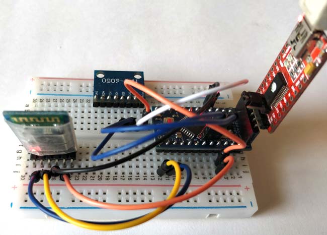
The complete circuit diagram for this Arduino Tilt Sensor Project is shown below. It just has only three components and can be easily built over the breadboard.
The MPU6050 communicates with the help of I2C and hence the SDA pin is connected to the A4 pin of Arduino which is the SDA pin and the SCL pin is connected to the A5 pin of Arduino. The HC-06 Bluetooth Module works with the help of Serial communication hence the Rx pin of Bluetooth is connected to pin D11 and the Tx pin of Bluetooth is connected to pin D10 of the Arduino. These pin D10 and D11 will be configured as Serial pin by programming the Arduino. The HC-05 module and the MSP6050 module operates on +5V and hence they are powered by the Vcc pin of the Arduino as shown above.
I used some breadboard connecting wires and built the set-up over a small breadboard. Once the connections are done my board looks like this below.
Powering your setup:
You can either power your circuit through the FTDI programming board as I have did, or use a 9V battery or 12V adapter and connect it to the Raw pin of the Arduino pro mini. The Arduino Pro-mini has an in-built voltage regulator which would convert this external voltage regulated +5V.

Programming your Arduino:
Once the hardware is ready, we can start programming our Arduino. As always the complete code for this project can be found at the bottom of this page. But to understand the project better I have broken the code to small chinks and explained them as steps below.
The first step would be interfacing the MPU6050 with Arduino. For this project we are going to use the library developed by Korneliusz which can be downloaded from link below
MPU6050 Liberty - Korneliusz Jarzebski
Download the ZIP file and add it to your Arduino IDE. Then head on to File->Examples->Arduino_MPU6050_Master -> MPU6050_gyro_pitch_roll_yaw. This will open the example program that uses the library that we just downloaded. So click on upload and wait for the program to be uploaded to your Arduino Pro mini. Once that is done open your serial monitor and set your baud rate to 115200 and check if you are getting the following.
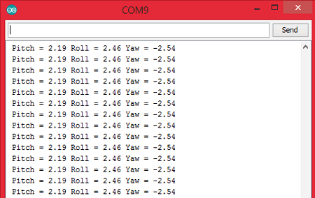
Initially, all the three values will be as zero, but as you move your breadboard you can observe these values getting changed. If they change it means your connection is correct, else check your connections. Take some time here notice how the three values Pitch Roll and Yaw vary according to the way you tilt your sensor. If you get confused press the reset button on the Arduino and the values will be initialized to zero again, then tilt the sensor in one direction and check which values are varying. The below picture will help you to understand better.
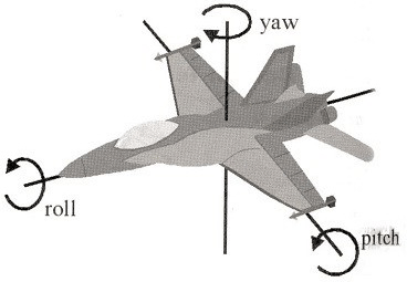
Out of these three parameters we are interested only in Roll and Pitch. The Roll value will tell us about the inclination in X-axis and the Pitch value will tell us about the inclination in Y-Axis. Now that we have understood the basics lets actually start programming the Arduino to read these values send it over to Arduino via Bluetooth. As always let's start by including all the libraries needed for this project
#include <Wire.h> //Lib for IIC communication
#include <MPU6050.h> //Lib for MPU6050
#include <SoftwareSerial.h>// import the serial library
Then we initialize the software serial for the Bluetooth module. This is possible because of the Software Serial library in Arduino, the IO pins can be programmed to work as Serial pins. Here we are using the digital pins D10 and D11, where D10 id Rx and D11 is Tx.
SoftwareSerial BT(10, 11); // RX, TX
Followed by that we initialize the variables and objects needed for the program and move onto the setup() function where we specify the baud rate for Serial monitor and Bluetooth. For HC-05 and HC-06 the baud rate is 9600 so it is mandatory to use the same. Then we check if the IIC bus of Arduino is connected to MPU6050 if not we print a warning message and remain there as long as the device is connected. After that, we calibrate the Gyro and set its threshold values using its respective functions as shown below.
void setup()
{
  Serial.begin(115200);
  BT.begin(9600); //start the Bluetooth communication at 9600 baudrate
  // Initialize MPU6050
  while(!mpu.begin(MPU6050_SCALE_2000DPS, MPU6050_RANGE_2G))
  {
    Serial.println("Could not find a valid MPU6050 sensor, check wiring!");
    delay(500);
  }
  mpu.calibrateGyro();   // Calibrate gyroscope during start
  mpu.setThreshold(3); //Controls the sensitivty
}
The line “mpu.calibrateGyro();” calibrate the MPU6050 for the position it is currently placed at. This line can be called multiple times inside the program whenever the MPU6050 needs to be calibrated and all values are to be set to zero. “mpu.setThreshold(3);” this function controls how much the value varies for the movement on sensor a too low value will increase the noise so be careful while fiddling around with this.
Inside the void loop(), we repeatedly read the values of Gyroscope and Temperature sensor calculate the value of pitch, roll and yaw, send it to the Bluetooth module. The following two lines will read the raw Gyro values and the temperature value
  Vector norm = mpu.readNormalizeGyro();
  temp = mpu.readTemperature();
Next, we calculate the pitch, roll, and yaw by multiplying with time step and adding it up to the previous values. A timeStep is nothing but the interval between successive readings.
  pitch = pitch + norm.YAxis * timeStep;
  roll = roll + norm.XAxis * timeStep;
  yaw = yaw + norm.ZAxis * timeStep;
To understand time step better let’s take a look at the below line. This line is placed to read the values from MPU6050 exactly at an interval of 10mS or 0.01 Second. So we declare the value of timeStep as 0.01. And use the line below to hold the program if there if there is more time left. (millis() – timer()) gives the time taken for the program to execute so far. We just subtract it with 0.01 seconds and for the remaining time we just hold our program there using the delay function.
delay((timeStep*1000) - (millis() - timer));
Once we are done reading and calculating the values, we can send them over to our phone via Bluetooth. But there is a catch here. Bluetooth module that we are using can send only 1 byte (8 bits) which allows us to send numbers only from 0 to 255. So we have to split our values and map it inside this range. This is done by the following lines
  if (roll>-100 && roll<100)
  x = map (roll, -100, 100, 0, 100);
  if (pitch>-100 && pitch<100)
  y = map (pitch, -100, 100, 100, 200);
  if (temp>0 && temp<50)
  t = 200 + int(temp);
As you can figure it out, the value of roll is mapped into 0 to 100 into the variable x and pitch is mapped to 100 to 200 into the variable y and temp is mapped into 200 and above into the variable t. We can use the same information to retrieve the data from what we have sent. Finally we write these values via the Bluetooth using the following lines.
  BT.write(x);
  BT.write(y);
  BT.write(t);
If you have understood the complete program, scroll down to have a look at the program and upload it to the Arduino board.
Preparing the Android Application using Processing:
The android application for this Arduino Inclinometer was developed using the Processing IDE. This is very much similar to Arduino and can be used to create system application, Android application, web designs and much more. We have already used processing to develop some of our other cool projects that are listed below
- Ping Pong Game using Arduino
- Smart Phone Controlled FM Radio using Processing.
- Arduino Radar System using Processing and Ultrasonic Sensor
However, it is not possible to explain the complete code on how to create this application. So you have two ways to go over this. Either you can download the APK file from the below link and install the android application directly on your phone. Or scroll below to find the complete processing code and learn by yourself how it works
Android APK File for Arduino Inclinometer (Right Click and Save Link As...)
Note: The application by default only connects to Bluetooth devices named as “HC-06”
Understanding the Processing Code:
For those who chose the later of understanding the processing code, I would like to explain few important points. The code requires Android mode of processing to be functioning which in turn needs the Android SDK files. The installation is a bit bulky but it is all worth it. Second, if you are trying to use this code given below then you will need the following ZIP file which contains the data file along with the code
Processing program ZIP file for Arduino Inclinometer
Inside the ZIP file, you can find a folder called data which consists of all the images and other sources that is to be loaded into the android application. The below line decides to which name the Bluetooth should automatically connect to
bt.connectToDeviceByName("HC-06");
Inside the draw() function, the things will be executed repeatedly here we draw the images, display the text and animate the bars based on the values form the Bluetooth module. You can check what happens inside each function by reading through the program.
void draw() //The infinite loop
{
 background(0);
 imageMode(CENTER);
 image(logo, width/2, height/1.04, width, height/12);
  load_images();
  textfun();
  getval();
}
Finally, there is one more important thing to explain, remember that we split the value of pitch, roll and temp to 0 to 255. So here we again bring it back to normal values by reverse mapping it to normal values.
  if (info<100 && info>0)
  x = map(info, 0, 100, -(width/1.5)/3, +(width/1.5)/3);//x = info;
  else if (info<200 && info>100)
  y = map(info, 100, 200, -(width/4.5)/0.8, +(width/4.5)/0.8);//y = info;
  else if (info>200)
  temp = info -200;
  println(temp,x,y);
There are much better ways to get data from a Bluetooth module to phone, but since this is just a hobby project we have ignored them, you can dig deep if interested.

Working of Arduino Inclinometer:
After you get ready with the Hardware and Application, it’s time to have fun with what we have built. Upload the Arduino Code to the board, you can also remove the comments on Serial.println lines and check if the hardware is working as expected using the serial monitor. Anyway, that is completely optional.
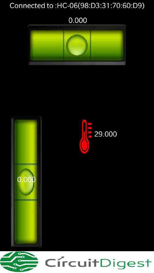
Once the code is uploaded, launch the Android application on your mobile phone. The application should automatically connect to your HC-06 module and it will display “Connect to: HC-06” on the top of the application as shown below.
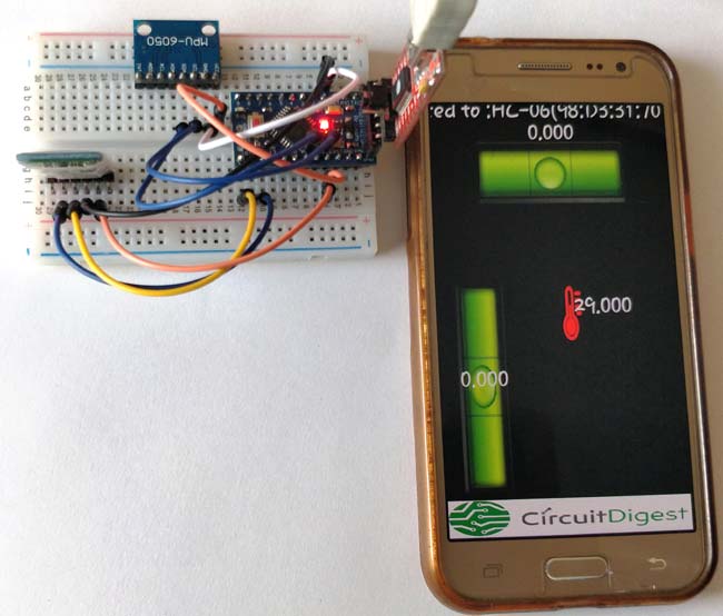
Initially, all the values will be zero except for the temperature value. This is because the Arduino has calibrated the MPU-6050 for this position as a reference, now you can tilt the hardware and check that the values on the mobile application are also changing along with the animation. The complete working of the application can be found at the video given below. So now you can place the breadboard anywhere and check if the surface is perfectly leveled.
Hope you understood the project and learned something useful out of it. If you have any doubt please use the comment section below or the forums to get it resolved.
Complete Project Code
/*
    MPU6050 Librarey: https://github.com/jarzebski/Arduino-MPU6050  (c) 2014 by Korneliusz Jarzebski

*/
#include <Wire.h> //Lib for IIC communication

#include <MPU6050.h> //Lib for MPU6050

#include <SoftwareSerial.h>// import the serial library
SoftwareSerial BT(10, 11);  // RX, TX
MPU6050 mpu;
unsigned long timer = 0;
unsigned long timer2 = 0;
float timeStep = 0.01;

float pitch = 0;

float roll = 0;

float yaw = 0;

float temp =0;
void setup()

{

  Serial.begin(115200);
  BT.begin(9600); //start the Bluetooth communication at 9600 baudrate
  // Initialize MPU6050

  while(!mpu.begin(MPU6050_SCALE_2000DPS, MPU6050_RANGE_2G))

  {

    Serial.println("Could not find a valid MPU6050 sensor, check wiring!");

    delay(500);

  }


  mpu.calibrateGyro();   // Calibrate gyroscope during start
  mpu.setThreshold(3); //Controls the sensitivty

}
void loop()

{

  timer = millis();
  //Read Gyro and Temperature sensor values

  Vector norm = mpu.readNormalizeGyro();

  temp = mpu.readTemperature();
  // Calculate Pitch, Roll and Yaw

  pitch = pitch + norm.YAxis * timeStep;

  roll = roll + norm.XAxis * timeStep;

  yaw = yaw + norm.ZAxis * timeStep;
  // Print values

  Serial.print(" Pitch = ");

  Serial.print(pitch);

  Serial.print(" Roll = ");

  Serial.print(roll);

  Serial.print(" Yaw = ");

  Serial.print(yaw);

  Serial.print(" Temp = ");

  Serial.print(temp);

  Serial.println(" *C");
  delay((timeStep*1000) - (millis() - timer)); //makes sure we read only at a an interval of 0.01 secounds
  if ((millis()-timer2) > 200)

  send_BT();

}
void send_BT()

{

  int t;

  int x;

  int y;
  if (roll>-100 && roll<100)

  x = map (roll, -100, 100, 0, 100);
  if (pitch>-100 && pitch<100)

  y = map (pitch, -100, 100, 100, 200);
  if (temp>0 && temp<50)

  t = 200 + int(temp);


  BT.write(x);

  BT.write(y);

  BT.write(t);
  timer2 = millis();

}
Comments
Hello I'm Norbert
Hello I'm Norbert
It is a great project
I trid to make it, but i have got a problem
I built it, and on the serial monitor everything is fine.
I connected to my mobile, the app is connected, but nothing happens,
What do i wrong?
looking forward to your message.
Norbert.
(Sorry for my bad english)
Make sure the bluetooth
Make sure the bluetooth module is working. You can use other bluetooth terminal apps like BT terminlal to check if you are getting any data from the arduino
Ok ,thanks.
Ok ,thanks.
That was the problem.
Th bt module is connevted, but not do anything.
I do a reset (factory default) and than its work.
Thanks
source code to apk?
Hello, I'm a student from Korea and this post has helped me a lot. You are a real gem in the internet-arduino world.
I was wondering, can you tell me how to compile the source files of the apk to apk again?
I want to modify some images and test it on my smartphone.
Hello my name is Richard and
Hello my name is Richard and new to this site.
I have a problem, i built the the project to the instruction's and is all working and will connect to a different
BT terminal,but not to the app provided. has anyone had a similar problem??
Many thanks Richard.

It is really useful for my project thank you