

A Power supply unit is a very commonly used tool by most engineers during the development stage. I personally use it a lot when experimenting with my circuit designs on Breadboard or to power up a simple module. Most of the digital circuits or embedded circuits have a standard operating voltage of either 5V or 3.3V, so I decided to build a Power supply which can supply 5V/3.3V on the power rails of the breadboard and fits snugly on the breadboard.
The complete power supply will be designed on PCB using EasyEDA. The circuit utilises a 7805 to supply 5V and a LM317 to supply 3.3V with a maximum current rating of 1.5A which is high enough to source for digital IC’s and Microcontroller circuits. So let’s get started....
Materials Required
- LM317 Variable Voltage Regulator
- 7805
- DC Barrel Jack
- 330ohm and 560 ohm Resistor
- 0.1 and 1uF capacitor
- LED Light
- Male Bergstik
- PCB (From JLCPCB)
Circuit Diagram
The complete circuit diagram for this Breadboard Power Supply project is shown below. The circuit was created using Easy EDA.

In order to easily understand the circuit, it is segmented into four parts. The Top left and Bottom left part is the 5V regulator and 3.3V regulator respectively. The top right and bottom right part is the header pins from which we can get either 5V or 3.3V as required by changing the position of the jumper.
For people who are new to labels, it is just a virtual wire that is used in circuit diagrams for making is more neat and easy to understand. In the above circuit the names +12V, +5V and +3.3V are labels. Any two places where +12V label is written is actually connected by a wire, the same is applicable for other two labels +5V and +3.3V as well.
+5V Regulator circuit
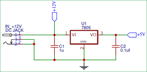
We have used a 7805 Positive voltage regulator to obtain a regulated +5V supply. The input of the IC is from a 12V Adapter fed in through a DC barrel Jack. To remove ripples we have used a 1uF capacitor in the input section and a 0.1uF capacitor at the output section. The regulated +5V output voltage can be obtained for pin 3. With proper heat sink we can get around 1.5A form the 7805 IC.
+3.3V Regulator Circuit
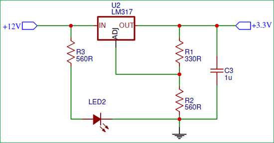
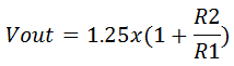
Similarly to obtain +3.3V we have used a Variable voltage regulator LM317. LM317 is an adjustable voltage regulator which takes an input voltage of 12V and provides a fixed output voltage of 3.3V. The output voltage Vout is dependent on external resistor values R1 and R2, according to the following equation:
The recommended value for R1 is 240Ω but it can also be some other value between 100Ω to 1000Ω. We can use this online calculator to calculate the values of R1 and R2, I have fixed the value of R1 to be 330R and the value of output voltage to be 3.3V. After pressing the calculate button I got the following result.
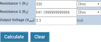
Since we do not have a 541.19 ohm resistor we have used the closest possible value which is 560 ohm. We have also added an LED through another 560 ohm resistor which will act as a power indicator.
Placing the header pins
In the above two block of circuits we have regulated +5V and +3.3V form a 12V source. Now we have to provide an option to the user to select between the +5V voltage or the +3.3V voltage as required by the user. To do that we have used male header pins with jumpers. The User can toggle the jumper to select between the +5V and +3.3V voltage values. We have also placed another header pin at the bottom of the PCB so that we can mount it directly on top of a Breadboard.

PCB Design using EasyEDA
To design this Bread board power supply, we have chosen the online EDA tool called EasyEDA. I have previously used EasyEDA many times and found it very convenient to use since it has a good collection of footprints and it is open-source. After designing the PCB, we can order the PCB samples by their low cost PCB fabrication services. They also offer component sourcing service where they have a large stock of electronic components and users can order their required components along with the PCB order.
While designing your circuits and PCBs, you can also make your circuit and PCB designs public so that other users can copy or edit them and can take benefit from your work, we have also made our whole Circuit and PCB layouts public for this circuit, check the below link:
https://easyeda.com/circuitdigest/breadboard-power-supply-circuit
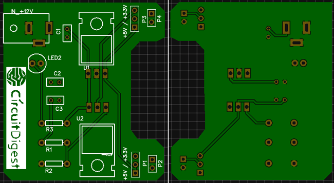
You can view any Layer (Top, Bottom, Topsilk, bottomsilk etc) of the PCB by selecting the layer form the ‘Layers’ Window.
You can also view the PCB, how it will look after fabrication using the Photo View button in EasyEDA:
Calculating and Ordering Samples online
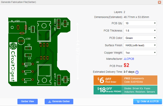
After completing the design of this Bread board power supply PCB, you can order the PCB through JLCPCB.com. To order the PCB from JLCPCB, you need Gerber File. To download Gerber files of your PCB just click the Generate Fabrication File button on EasyEDA editor page, then download the Gerber file from there or you can click on Order at JLCPCB as shown in below image. This will redirect you to JLCPCB.com, where you can select the number of PCBs you want to order, how many copper layers you need, the PCB thickness, copper weight, and even the PCB color, like the snapshot shown below:
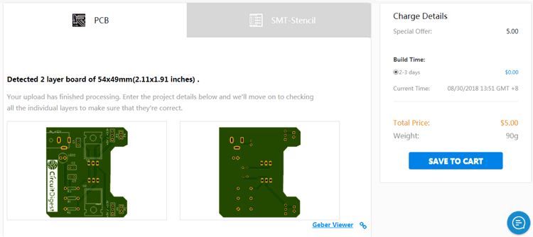
After you have selected all of the options, click “Save to Cart” and then you will be taken to the page where you can upload your Gerber File which we have downloaded from EasyEDA. Upload your Gerber file and click “Save to Cart”. And finally click on Checkout Securely to complete your order, then you will get your PCBs a few days later. They are fabricating the PCB at very low rate which is $2. Their build time is also very less which is 48 hours with DHL delivery of 3-5 days, basically you will get your PCBs within a week of ordering.
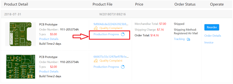
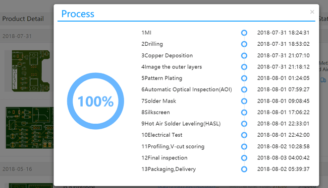
After ordering the PCB, you can check the Production Progress of your PCB with date and time. You check it by going on Account page and click on "Production Progress" link under the PCB like, shown in below image.
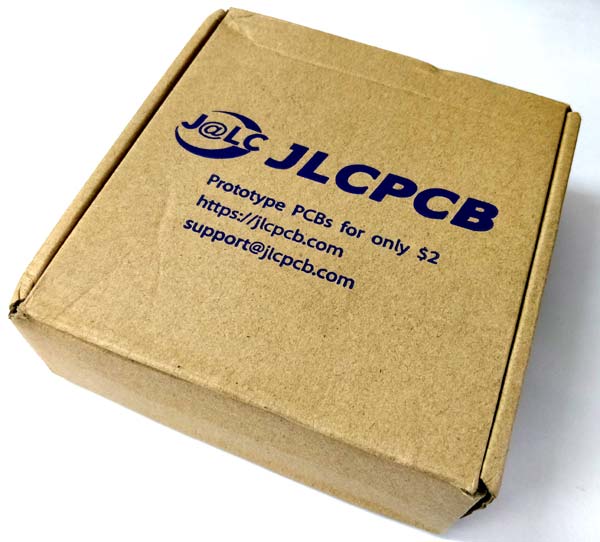
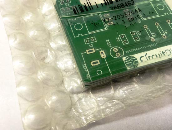
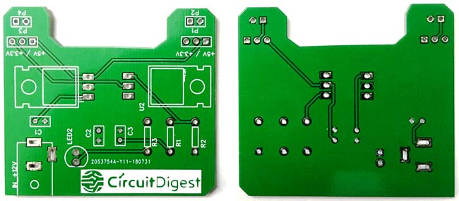
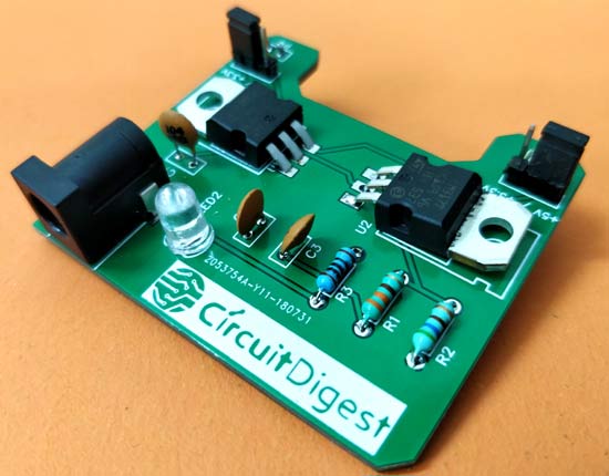
After few days of ordering PCB’s I got the PCB samples in nice packaging as shown in below pictures.
And after getting these pieces I have soldered all the required components over the PCB.
Working of Breadboard Power Supply Circuit
After assembling your PCB make sure there is no cold soldering and clean away all the excess flux on your board. Fix the board on top your breadboard and it should sit snug between both the power rails of your breadboard, now use a 12V adapter to Power your board through the DC jack and you should see the power LED (here white colour) turning on. Then, you can set the jumper to either 5V side or 3.3V side using the silkscreen information. Make sure you use the jumpers else we will not get any voltage on the output side.
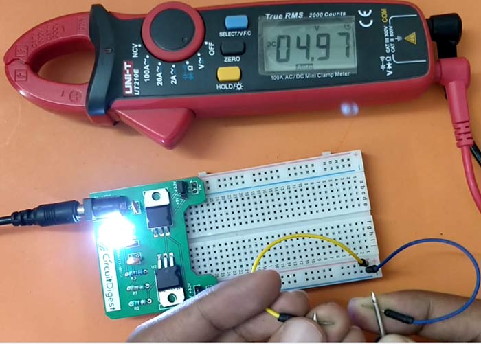
In the above image I have placed the jumper to provide +5V and measuring the same using a multimeter which also shows 4.97V which is close enough. Similarly, you can also check of 3.3V. The complete working and testing of the project is also shown in the video below.
Now, you can use this board to power all your future electronics designs on your breadboard with either 5V or 3.3V. Hope you understood the project and enjoyed building it if you have any problem in getting it to work you can post it down in the comment section or you can use our forums for more technical quires.
Comments
Spencer knows what he is
Spencer knows what he is talking about! nice tips
5v and 3.3v power supply
If I want to add 9v and 12v power supply also then which components i need and how I connect all the components. Can you please tell me ?
compnents value ?
what are the values of C1 C2 C3 and R3 ?
I see 104 on capacitor C1 and C3 and you précognize 1µ ?
The values are mentioned in
The values are mentioned in the circuit diagram
https://circuitdigest.com/fullimage?i=circuitdiagram/Circuit-Diagram-fo…
1. What are the Watt values…
1. What are the Watt values for R1, R2, and R3?
2. I was getting DRC Errors and discovered two traces between R3 12v and U2_3 12volt. One trace was on the top layer and the second was on the bottom layer. I removed the trace on the bottom layer to clear up the Errors.

For anyone wanting to get closer to the 3.3v (if needed) you could use 2 resistors , one a 150Ohm in series with a 390Ohm for 540Ohm (+0.22% out) or one of the LMS8117AMP-3.3 fixed output 3.3v 1 amp devices instead, also think about using a 9 volt input as the regulator has to work less hard to make the voltage transition, and one last thing, keep the thermal "tabs" for the regulators non solder masked so you can use the copper of the PCB as additional heat syncing with the use of a little thermal compound and a nut/bolt or solder it directly.
Have Fun.