

16×2 LCD is named so because; it has 16 Columns and 2 Rows. There are a lot of combinations available like, 8×1, 8×2, 10×2, 16×1, etc. But the most used one is the 16*2 LCD, hence we are using it here.
All the above mentioned LCD display will have 16 Pins and the programming approach is also the same and hence the choice is left to you. Below is the Pinout and Pin Description of 16x2 LCD Module:

|
Sr. No |
Pin No. |
Pin Name |
Pin Type |
Pin Description |
Pin Connection |
|
1 |
Pin 1 |
Ground |
Source Pin |
This is a ground pin of LCD |
Connected to the ground of the MCU/ Power source |
|
2 |
Pin 2 |
VCC |
Source Pin |
This is the supply voltage pin of LCD |
Connected to the supply pin of Power source |
|
3 |
Pin 3 |
V0/VEE |
Control Pin |
Adjusts the contrast of the LCD. |
Connected to a variable POT that can source 0-5V |
|
4 |
Pin 4 |
Register Select |
Control Pin |
Toggles between Command/Data Register |
Connected to a MCU pin and gets either 0 or 1. 0 -> Command Mode 1-> Data Mode |
|
5 |
Pin 5 |
Read/Write |
Control Pin |
Toggles the LCD between Read/Write Operation |
Connected to a MCU pin and gets either 0 or 1. 0 -> Write Operation 1-> Read Operation |
|
6 |
Pin 6 |
Enable |
Control Pin |
Must be held high to perform Read/Write Operation |
Connected to MCU and always held high. |
|
7 |
Pin 7-14 |
Data Bits (0-7) |
Data/Command Pin |
Pins used to send Command or data to the LCD. |
In 4-Wire Mode Only 4 pins (0-3) is connected to MCU In 8-Wire Mode All 8 pins(0-7) are connected to MCU |
|
8 |
Pin 15 |
LED Positive |
LED Pin |
Normal LED like operation to illuminate the LCD |
Connected to +5V |
|
9 |
Pin 16 |
LED Negative |
LED Pin |
Normal LED like operation to illuminate the LCD connected with GND. |
Connected to ground |
It is okay if you do not understand the function of all the pins, I will be explaining in detail below. Now, let us turn back our LCD:
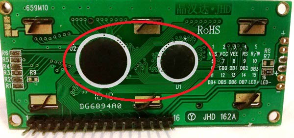
Okay, what is this two black circle like things on the back of our LCD?
These black circles consist of an interface IC and its associated components to help us use this LCD with the MCU. Because our LCD is a 16*2 Dot matrix LCD and so it will have (16*2=32) 32 characters in total and each character will be made of 5*8 Pixel Dots. A Single character with all its Pixels enabled is shown in the below picture.
![]()
So Now, we know that each character has (5*8=40) 40 Pixels and for 32 Characters we will have (32*40) 1280 Pixels. Further, the LCD should also be instructed about the Position of the Pixels.
It will be a hectic task to handle everything with the help of MCU, hence an Interface IC like HD44780 is used, which is mounted on LCD Module itself. The function of this IC is to get the Commands and Data from the MCU and process them to display meaningful information onto our LCD Screen.
Let’s discuss the different type of mode and options available in our LCD that has to be controlled by our Control Pins.
4-bit and 8-bit Mode of LCD:
The LCD can work in two different modes, namely the 4-bit mode and the 8-bit mode. In 4 bit mode we send the data nibble by nibble, first upper nibble and then lower nibble. For those of you who don’t know what a nibble is: a nibble is a group of four bits, so the lower four bits (D0-D3) of a byte form the lower nibble while the upper four bits (D4-D7) of a byte form the higher nibble. This enables us to send 8 bit data.
Whereas in 8 bit mode we can send the 8-bit data directly in one stroke since we use all the 8 data lines.
Now you must have guessed it, Yes 8-bit mode is faster and flawless than 4-bit mode. But the major drawback is that it needs 8 data lines connected to the microcontroller. This will make us run out of I/O pins on our MCU, so 4-bit mode is widely used. No control pins are used to set these modes. It's just the way of programming that change.
Read and Write Mode of LCD:
As said, the LCD itself consists of an Interface IC. The MCU can either read or write to this interface IC. Most of the times we will be just writing to the IC, since reading will make it more complex and such scenarios are very rare. Information like position of cursor, status completion interrupts etc. can be read if required, but it is out of the scope of this tutorial.
The Interface IC present in most of the LCD is HD44780U, in order to program our LCD we should learn the complete datasheet of the IC. The datasheet is given here.
LCD Commands:
There are some preset commands instructions in LCD, which we need to send to LCD through some microcontroller. Some important command instructions are given below:
|
Hex Code |
Command to LCD Instruction Register |
|
0F |
LCD ON, cursor ON |
|
01 |
Clear display screen |
|
02 |
Return home |
|
04 |
Decrement cursor (shift cursor to left) |
|
06 |
Increment cursor (shift cursor to right) |
|
05 |
Shift display right |
|
07 |
Shift display left |
|
0E |
Display ON, cursor blinking |
|
80 |
Force cursor to beginning of first line |
|
C0 |
Force cursor to beginning of second line |
|
38 |
2 lines and 5×7 matrix |
|
83 |
Cursor line 1 position 3 |
|
3C |
Activate second line |
|
08 |
Display OFF, cursor OFF |
|
C1 |
Jump to second line, position 1 |
|
OC |
Display ON, cursor OFF |
|
C1 |
Jump to second line, position 1 |
|
C2 |
Jump to second line, position 2 |
Check our LCD interfacing Articles with different Microcontrollers:
Use a transistor
Hi aparna,
You should not drive the Relay directly from an Arduino I/O pin. If your Relay is a 5V relay you can use the circuit shown in the link below
https://circuitdigest.com/fullimage?i=circuitdiagram_mic/Visitor-Counter-Circuit1.gif (Check the relay driving part alone)
As shown in the circuit if you use a transistor like BC547 and current limiting resistor, you should be able to toggle the relay without any problem.
The reason is that when you trigger a relay directly from Arduino, the current provided by the I/O pin will not be enough and hence there will be a voltage drop (In your case 2.7) on your Arduino pin.
Hence we use the I/O pin to trigger the transistor, which closes the connection between a constant +5V and the relay.
16X2 character LCD Display unit for replacement of potter panel
Need advise on availability and compatibility . Required 12 unit.
wrong matrix
the hex command 38 is used for making 5x8 dot martix not for 5x7
How to find out what LCD I have ...
Hi
Tank you for your interesting and usefull articel. Question: Is it possible to find out a pinout from an older, used LCD display? I have different, old displays I got out of still working but sorted out electronic gears like server nodes, video recorders , ... , you name it ... . Of course, I would like to use them and I asked myself, if it is possible, to find out how the pinout for that devcices is.
Yes it is possible!! to which
Yes it is possible!! to which motor u r trying? providing pics will help

In my project i have to connect a relay to digital pins of the arduino uno board. But I couldn't control the relay since the output is 2.18v. Could you please guide me what should i do.