
In this project, we are going to make an AC Voltage Measuring Device using Arduino, which will measure the voltage of Alternating Current Supply at our home. We are going to print that voltage on serial monitor of Arduino IDE as well as show on the multimeter.
Making a Digital Voltmeter is a lot easy than making an analog one because in case of analog voltmeter you must have good knowledge of physical parameters like torque, friction losses etc. whereas in case of digital voltmeter you can just use a LCD or LED matrix or even your laptop (as in this case) to print the voltage values for you. Here are some Digital Voltmeter Projects:
- Simple Digital Voltmeter Circuit with PCB using ICL7107
- LM3914 Voltmeter Circuit
- 0-25V Digital Voltmeter using AVR Microcontroller
Required Components:
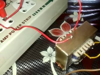
- One 12-0-12 transformer
- 1N4007 diode
- 1uf capacitor
- Resistors 10k; 4.7k.
- Zener diode(5v)
- Arduino UNO
- Connecting wires
Arduino Voltmeter Circuit Diagram:

Circuit Diagram for this Arduino Voltmeter is shown above.
Connections:
- Connect high voltage side(220V) of transformer to the mains supply and low voltage(12v) to the voltage divider circuit.
- Connect 10k resistor in series with 4.7k resistor but make sure to take voltage as input across 4.7k resistor.
- Connect diode as shown.
- Connect capacitor and zener diode across 4.7k
- Connect a wire from n-terminal of diode to the analog pin A0 of Arduino.
** Note: Do connect ground pin of Arduino to the point as shown in the figure or circuit will not work.
Need of voltage divider circuit?
As we are using 220/12 v transformer, we get 12 v on l.v side. Since this voltage is not suitable as input for Arduino we need a voltage divider circuit which can give suitable voltage value as input to Arduino
.
Why diode and capacitor is connected?
Since Arduino do not take negative voltage values as input, we first need to remove negative cycle of step down AC so that only positive voltage value is taken by Arduino. Hence diode is connected to rectify the step down voltage. Check our Half wave rectifier and Full wave Rectifier circuit to learn more about rectification.
This rectified voltage is not smooth as it contains large ripples which cannot give us any exact analog value. Hence capacitor is connected to smooth out the a.c signal.
Purpose of zener diode?
Arduino can get damage if voltage greater than 5v is fed to it. Hence a 5v zener diode is connected to ensure safety of Arduino which breakdowns in case this voltage exceeded 5v.
Working of Arduino based AC Voltmeter:
1. Step down voltage is obtained on l.v side of transformer which is suitable to use across normal power rating resistors.
2. Then we get suitable voltage value across 4.7k resistor
Maximum voltage that can be measured is found by simulating this circuit on proteus (explained in simulation section).
3. Arduino takes this voltage as input from pin A0 in form of analog values between 0 to 1023. 0 being 0 volt and 1023 being 5v.
4. Arduino then converts this analog value into corresponding mains a.c. voltage by a formula. (Explained in code section).
Simulation:

Exact circuit is made in proteus and then simulated. To find maximum voltage that this circuit can measure hit and trial method is used.
On making alternator’s peak voltage 440 (311 r.m.s), voltage on pin A0 was found to be 5 volts i.e. maximum. Hence this circuit can measure maximum 311 r.m.s voltage.
Simulation is performed for various voltages between 220 r.m.s to 440v.

Code Explanation:
Complete ArduinoVoltmeter Code is given at the end of this project and it is well explained through the comments. Here we are explaining few part of it.
m is the input analog value received on pin A0 i.e.,
m= pinMode (A0,INPUT) ; // set pin a0 as input pin
To assign variable n to this formula n=(m*.304177), first some sort of calculations is performed by using the data obtained in simulation section:
As seen in simulation photograph, 5v or 1023 analog value is obtained at pin A0 when input a.c voltage is 311volts. Hence:
1023 analog value corresponds to 311 volt mains supply
So any random analog value corresponds to (311/1023)*m where m is obtained analog value.
Hence we arrive at this formula:
n=(311/1023)*m volts or n=(m*.304177)
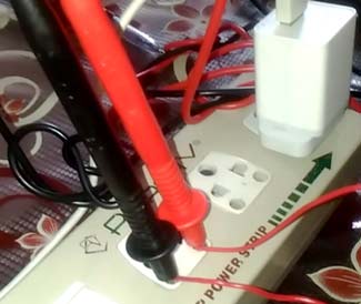
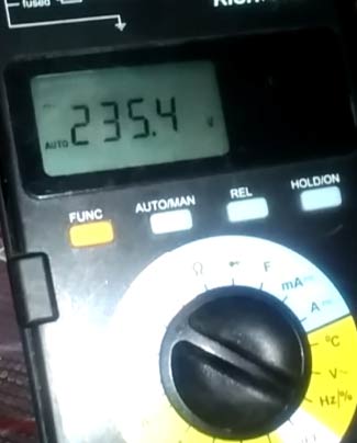
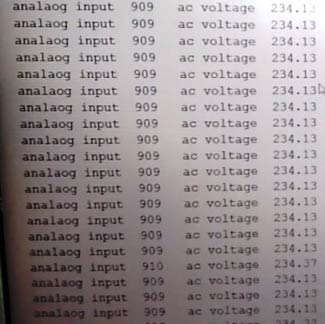
Now this voltage value is printed on the serial monitor by using serial commands as explained below. And also shown on the multimeter as demonstrated in the Video below.
Values printed on the screen are:
Analog input value as specified in the code:
Serial.print("   analog input  ") ; // this gives name which is “analog input”  to the printed analog value

Serial.print(m);// this simply prints the input analog value
Required a.c voltage as specified in the code:
 Serial.print("   ac voltage  ") ; // this gives name  “ac voltage”  to the printed analog value

 Serial.print(n) ;  // this simply prints the ac voltage value
Complete Project Code
int m;// initialise variable m

float n;//initialise variable n
void setup()

{

  pinMode(A0,INPUT); // set pin a0 as input pin

  Serial.begin(9600);// begin serial communication between arduino and pc

}
void loop()

{

  m=analogRead(A0);// read analog values from pin A0 across capacitor

   n=(m* .304177);// converts analog value(x) into input ac supply value using this formula ( explained in woeking section)


   Serial.print("   analaog input  " ) ; // specify name to the corresponding value to be printed

   Serial.print(m) ; // print input analog value on serial monitor

   Serial.print("   ac voltage  ") ; // specify name to the corresponding value to be printed

   Serial.print(n) ; // prints the ac value on Serial monitor

   Serial.println();

}
Comments
What simulation software did
What simulation software did you use?
The software used here is
The software used here is ISIS Proteus
current measurement
can you help me to measure a.c. current using CT...which will in range from 0 to 30 amp.
Hi Tunu, I am also trying to
Hi Tunu, I am also trying to read the AC voltage from a CT clamp. Would you mind sending me your schemtaics and code for ideas? I couldn't find your email address.
can we measure phase sequence
can we measure phase sequence using arduino?and how?
Above ac voltmeter using arduino
If we increase the supply ac voltage above 230v for checking overvoltage condition using arduino, then with respect to that increased voltage will the arduino recognize the fault of overvoltage or will the input given to arduino will also change with respect to changed supply voltage???
Do not do it. The arduino
Do not do it. The arduino will not recognize the over voltage and it might even damage your arduino
If there is too much noise in
If there is too much noise in you AC lines the result will not be stable. How much variation are you getting/.?
High frequencies
Hello all! How to make it work at higher (40 kHz) frequency and lower (<5V ) voltage?
Great work!!!!!
Great work!!!!!
what is the specification for transformer ??
current and voltage
Why do you use a 220/12V
Why do you use a 220/12V transformer?
Would it not be more accurate if you made a voltage divider to divide 220V (or 240V?) to 5V?
The transformer is also for
The transformer is also for SAFETY reasons. If you use a potential divider connected directly to the mains voltage that would be very dangerous. One fault and the whole circuit could become live. In addition some countries have two live wires/phases instead of live and neutral. You cannot safely assume that "Neutral" is the same voltage as the 0V from the Arduino power supply or USB. Do NOT omit the transformer.
Hello! How to set value of
Hello! How to set value of these transformer parameters in proteus for 220/12 V?
Primary Inductance
Secondary Inductance
Coupling Factor
Primary DC resistance
Secondary DC resistance
did u find the configurations
did u find the configurations for transformer?
if i check directly on
if i check directly on voltmeter it is showing 214 volts ... while on my serial monitor it is showing 311 volts... kindly help out

Great work, i'm trying to add phase sequence detection using opamp & times , any thoughts ?