
In this project, we are going to build a Transistor Based Simple Soil Moisture Detector Circuit. In this circuit, we have used an NPN transistor to detect soil moisture. This is very simple and interesting circuit for electronics lovers. This Soil moisture sensor circuit can be used in many applications like Automatic plant irrigation system, Greenhouse projects etc. If you do not want to build your own soil moisture circuit, you can also directly purchase it and use it with development boards like arduino. This is a more straight forward approach and lets you build many interesting projects easily. You can check out the Arduino soil moisture sensor tutorial for more information.
We also build IoT based Soil Moisture Monitoring Device, you can check out the demonstration video.
Components Required:
- BC547 transistor
- Buzzer
- Bread Board
- 1k Resistor (4)
- 50k POT
- LED
- Jumper wire
- 9V battery or supply
- LM7805 Voltage Regulator
- Soil Moisture Probe
Circuit Diagram:
Circuit Diagram of Soil Moisture Sensor Circuit is given below:

Working Explanation:
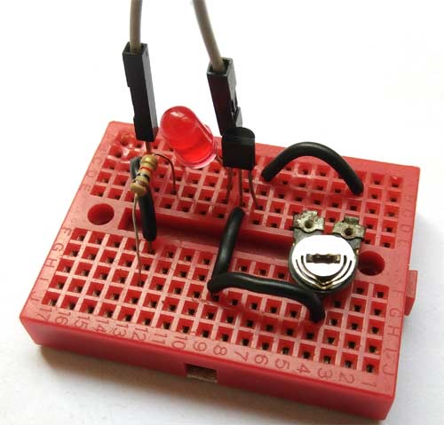
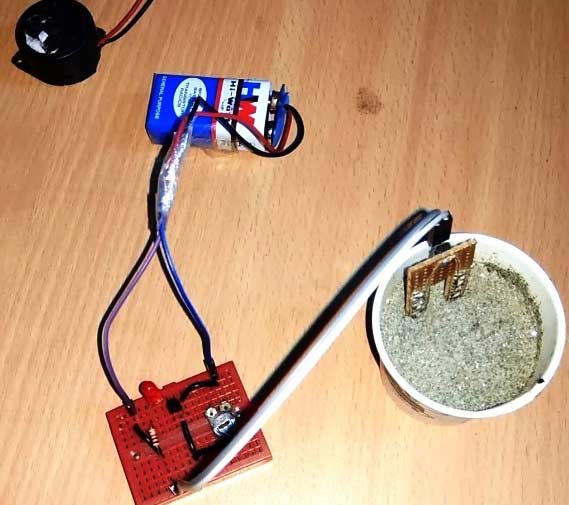
This Soil Moisture Detector Circuit is very simple. Here we have used a soil moisture detector probe to sense the moisture in the soil and an NPN transistor to trigger the Buzzer and LED. This soil moisture detector probe is homemade and built using general purpose PCB (Perf board). Buzzer and LED are used as an indication of soil moisture detection.
Working on this circuit is straightforward and clearly understandable. Here we have connected one wire of probe directly to VCC and another probe to the base of the transistor Q1 and 50k potentiometer RV1 is used for adjusting the sensitivity of the circuit. Now when there is no moisture in soil then probes does not allow 7805 to supply any voltage to the base of transistor Q1 so the LED and Buzzer remain turned off. Now, whenever both probes will come in contact with soil moisture or water then both the probe gets shorted because water/moisture is the conductor of current. And when probes get shorted then the base of the transistor gets connected to the output of 7805 IC.
As we know when we apply some voltage to the base of an NPN Transistor it gets turn on and allow current to pass through the collector to emitter. And as soon as transistor turns on it will trigger the Buzzer and LED. The buzzer will beep until probes detect soil moisture. We have covered detailed tutorial on soil moisture sensor module, so if you want to learn more about how does a soil moisture sensor work, please check out the linked article.
An LM7805 voltage regulator is used for limiting the input voltage to 5v. We have used 9v battery to supply power to this circuit.
The complete working of this circuit is shown in the Video below.
Comments
Yes you should be able to do it with a normal multimeter. For more accurate value measure the current and voltage drop and use ohms law to find the value of R
What if I don't have a voltage regulator? Would the circuit break?
Not really. You should not have any problem as long as you don't exceed the current or voltage ratings of led and buzzer.
where to connect the multimeter to measure resistance readings
the work i have read was of importance and i have really gained alot thanx so much

Is there a way one could measure the resistance to get a value? this would be useful to set variable thresholds for automatic watering systems.