
We all know about Electricity energy meters which are installed in everyone’s house or offices to measure the electricity consumption. At last of every month, many of us get worried about the high electricity bill and we have to look at the energy meter once in a while. But what if we can monitor our electricity uses from anywhere in the world and get an SMS/E-mail when your energy consumption reaches to a threshold value. Here we are building an IoT based Project of Energy Meter.
Previously we have built a Energy Meter circuit which sends you SMS about the bill using GSM module. In this project we make a Smart Electricity Energy meter using Arduino and ESP8266 Wi-Fi module which can not only sends you a SMS/Email of your electricity Bill but also you can monitor the energy uses anytime and from anywhere in the world. Here we have used a Current Sensor ACS712 to measure the energy consumption, we will discuss about it shortly.
We will take help of IFTTT platform to link our Wi-Fi to SMS/E-mail notifications. We will also use MQTT Dashboard Android App to monitor our Energy uses. So Lets Get started….
Materials Required:
- Arduino Uno
- ESP12/NodeMCU
- ACS712-30Amp Current sensor
- Any AC Appliance
- Male-Female Wires
Working of ACS712 Current Sensor:
Before we start building the project it is very important for us to understand the working of the ACS712 Current sensor as it is the key component of the project. Measuring current especially AC current is always a tough task due to the noise coupled with it improper isolation problem etc. But, with the help of this ACS712 module which was engineered by Allegro thing have become a lot easier.
This module works on the principle of Hall-effect, which was discovered by Dr. Edwin Hall. According his principle, when a current carrying conductor is placed into a magnetic field, a voltage is generated across its edges perpendicular to the directions of both the current and the magnetic field. Let us not get too deep into the concept but, simply put we use a hall sensor to measure the magnetic field around a current carrying conductor. This measurement will be in terms of millivolts which we called as the hall-voltage. This measured hall-voltage is proportional to the current that was flowing through the conductor.
The major advantage of using ACS712 Current Sensor is that is can measure both AC and DC current and it also provides isolation between the Load (AC/DC load) and Measuring Unit (Microcontroller part). As shown in the picture we have three pins on the module which are Vcc, Vout and Ground respectively.

The 2-pin terminal block is where the current carrying wire should be passed through. The module work on +5V so the Vcc should be powered by 5V and the ground should be connected to Ground of the system. The Vout pin has an offset voltage of 2500mV, meaning when there is no current flowing through the wire then the output voltage will be 2500mV and when current flowing is positive, the voltage will be greater than 2500mV and when the current flowing is negative, the voltage will be less than 2500mV.
We will be using the Analog pin of Arduino to read the output voltage (Vout) of the module, which will be 512(2500mV) when there is no current flowing through the wire. This value will reduce as the current flows in negative direction and will increase as the current flows in positive direction. The below table will help you understand how the output voltage and ADC value varies based on the current flowing through the wire.
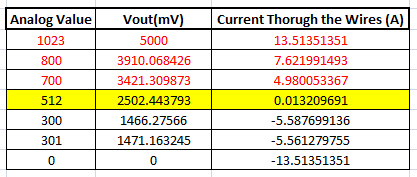
These values were calculated based on the information given in the Datasheet of ACS712. You can also calculate them using the below formulae:
Vout Voltage(mV) = (ADC Value/  1023)*5000
Current Through the Wire (A) = (Vout(mv)-2500)/185
Now, that we know how the ACS712 Sensor works and what we could expect from it. Let us proceed to the circuit diagram.
We have used this sensor to make Digital Ammeter Circuit using PIC Microcontroller and ACS712.
Circuit diagram:

Circuit diagram for IoT based Energy Meter using Arduino and NodeMCU is given above, connect ESP12 as below:
Connect Rx of ESP12 -> Tx of Arduino.
Connect Tx of ESP12 -> Rx of Arduino.
There is one analog pin available in NodeMCU (ESP12), we could use that pin but ESP series can take upto 3.3 volts on their pins. As we are using current sensor which can give upto 5 Volts so, it can damage our Wi-Fi module that’s why we are not using standalone NodeMCU.
To make output of current sensor 3.3V instead of 5V, we cannot use voltage divider circuit between Current sensor and analog pin of NodeMCU because as we discussed above about the current sensor that at 2.5Volts output, current is 0Amp.
So, Arduino will read the current sensor value through analog pin and send it to the Wi-Fi module ESP12 using Serial communication. Use voltage divider circuit at receiver pin of NodeMCU so that receiver pin can get upto 3.3 Voltage level.
To monitor our energy uses over the internet, we have to use MQTT broker. We will use MQTT broker as AdaFruit IO platform and follow the below process to make this IoT Energy Meter
- Setting up an AdaFruit account for storing Electricity meter readings.
- Create Applet in IFTTT for Triggering SMS/Email for Energy Meter
- Codes for Arduino and ESP12 Wi-Fi module.
Setting up an AdaFruit account for communication:
First, we will make a feed in AdaFruit IO. Feed stores the data sent by IFTTT. To make feed follow these steps:
Step 1:- Login to Adafruit IO with your credentials or Sign up if you don’t have an account.

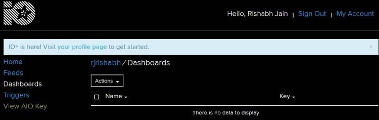
Step 2:-Click on My account -> Dashboard
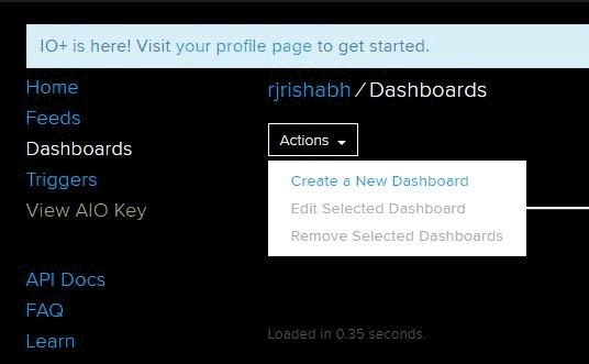
Step 3:-Click on Actions and Create a New Dashboard.
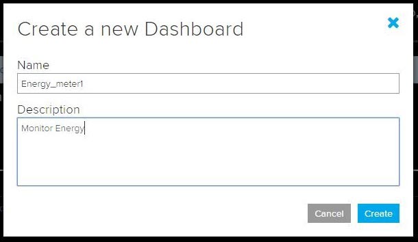
Step 4: Give name and description to your feed and click on Create.
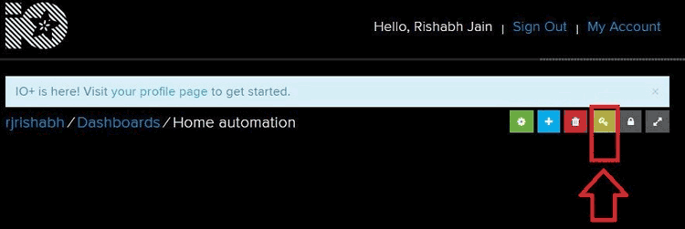
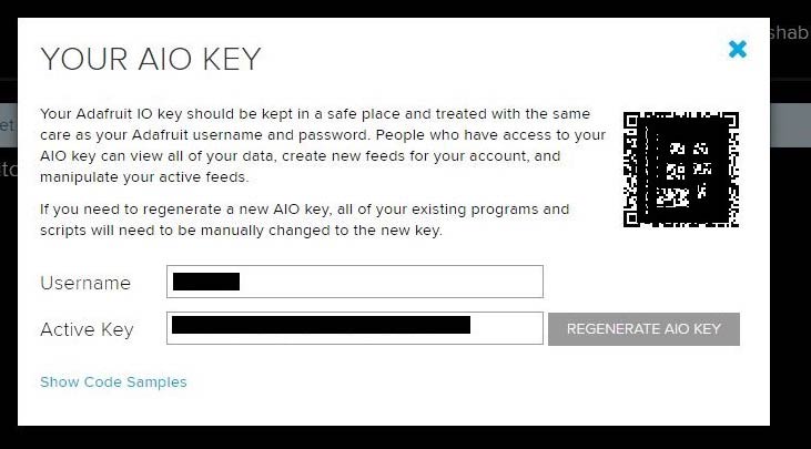
Step 5: Click on Key button and note down the AIO Keys, we will use this key in our code.
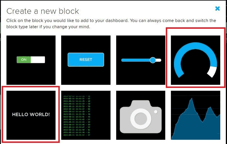
Step 6: Click on ‘+’ button to create a new block and click on Gauge to display Energy uses level. You can also use simple text box to display energy.
Step 7: Now, Enter Name of Feed and click on Create. Then Select the feed and click on Next step.
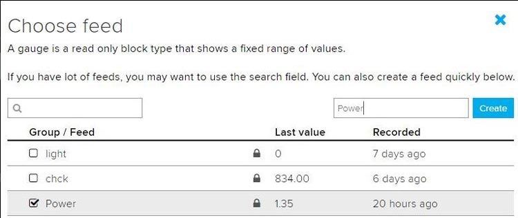
Step 8: In block settings, fill the min. and max values as 0 and 100 respectively or you can modify as you want.
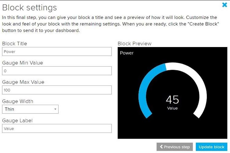
Step 9: Your Power feed is successfully created. Now, create feed to display Bill by clicking on “+” sign.
Now, we have to link AdaFruit IO to SMS/E-mail using IFTTT.

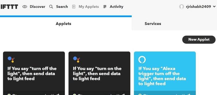
Create Applet in IFTTT for Triggering SMS/Email for Energy Meter:
Step 1: Login to IFTTT with your credentials.
Step 2: On My Applets, Click on New Applet
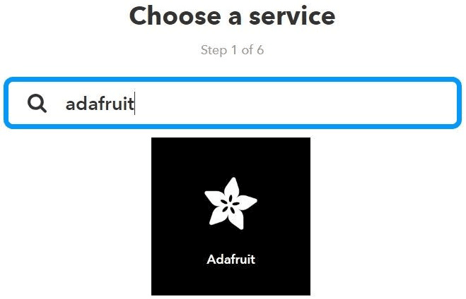
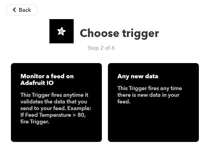
Step 3: Click on +this
Step 4: Search AdaFruit and click on it.
Step 5: Click on Monitor a feed on AdaFruit IO.
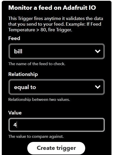
Step 6: Choose Feed as bill, Relationship as ‘equal to’ and the threshold value at which you want an E-mail. Click on Create action. I have used 4 as my threshold trigger value.
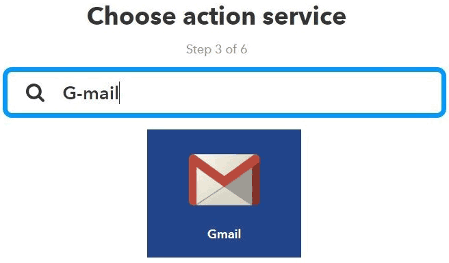
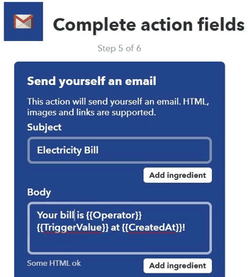
Step 7: Click on +that. Search for G-mail and click on it and Login with your g-mail credentials.
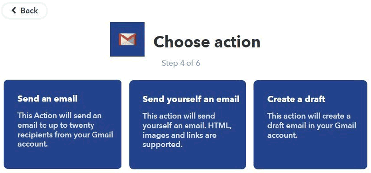
Step 8: Click on send yourself an email.
Step 9: Write your subject and body as shown and click to create.
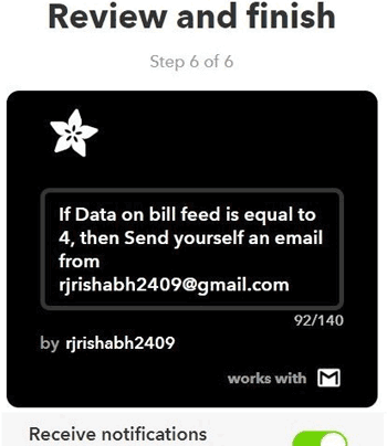
Step 10: Your ‘recipe’ is ready. Review it and click on finish.
Now, we are done with web integration. Let’s move on coding part..
Code and Explanation:
We are using serial communication between ESP12 and Arduino. So, we have to write code for both Arduino and NodeMCU for transmitting and receiving.
Code for Transmitter Part i.e. for Arduino Uno:
Complete Arduino code is given at the end of this tutorial. We will use library for Current sensor which can be downloaded from this Link.
This library has inbuilt function to calculate current. You can write your code to calculate current but this library has accurate current measuring algorithms.
First, include library for current sensor as:
#include "ACS712.h"
Make an array to store power for sending it to NodeMCU.
char watt[5];
Create an instance to use ACS712-30Amp at PIN A0. Change First argument if you are using 20Amp or 5 Amp variant.
ACS712 sensor(ACS712_30A, A0);
In setup function, define baud rate of 115200 to communicate with NodeMCU. Call sensor.calibrate() function for calibrating current sensor to get accurate readings.
void setup() {
  Serial.begin(115200);
  sensor.calibrate();
}
In loop function, we will call sensor.getCurrentAC(); function to get the current value and store in the float variable I. After getting current, calculate power using P=V*I formula. We use 230V because it is the common standard in European countries, Change to your local, if necessary
void loop() {
  float V= 230;
  float I = sensor.getCurrentAC();
  float P = V * I;
These lines convert power into Wh.
  last_time = current_time;
  current_time = millis();
  Wh = Wh+  P *(( current_time -last_time) /3600000.0) ;
Now, we have to convert this Wh into character form to send it to NodeMCU, for this dtostrf(); will convert a float to a char array so it can then be printed easily:
dtostrf(Wh, 4, 2, watt);
The format is:
dtostrf(floatvar, StringLengthIncDecimalPoint, numVarsAfterDecimal, charbuf);
Write this character array to serial buffer using Serial.write(); function. This will send Wh value to NodeMCU.
 Serial.write(watt);
  delay(10000);
}
Code for Receiver Part NodeMCU ESP12:
For this we need AdaFruit MQTT library which can be downloaded from this link.
Now, open Arduino IDE. Go to examples -> AdaFruit MQTT library -> mqtt_esp8266
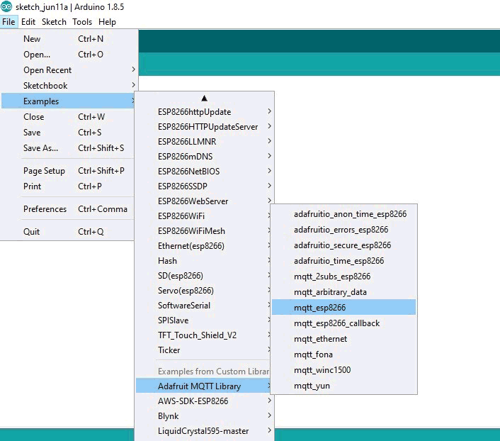
We will edit this code according to our AIO keys and Wi-Fi credentials and incoming serial data from the Arduino.
First, we included all the libraries for ESP12 Wi-Fi Module and AdaFruit MQTT.
#include <ESP8266WiFi.h>
#include "Adafruit_MQTT.h"
#include "Adafruit_MQTT_Client.h"
We define the SSID and Password for your Wi-Fi, from which you want to connect your ESp-12e.
#define WLAN_SSID       "xxxxxxxx"
#define WLAN_PASS       "xxxxxxxxxxx"
This section defines the AdaFruit server and server port which is fixed as “io.adafruit.com” and “1883” respectively.
#define AIO_SERVER      "io.adafruit.com"
#define AIO_SERVERPORT  1883
Replace these fields with your username and AIO keys which you have copied from AdaFruit site while making the Feed.
#define AIO_USERNAME    "********"
#define AIO_KEY         "******************************"
Then we have created an ESP12 WiFiClient class to connect to the MQTT server.
WiFiClient client;
Setup the MQTT client class by passing in the WiFi client and MQTT server and login details.
Adafruit_MQTT_Client mqtt(&client, AIO_SERVER, AIO_SERVERPORT, AIO_USERNAME, AIO_KEY);
Setup a feed called 'Power' and ‘bill’ for publishing to changes.
Adafruit_MQTT_Publish Power = Adafruit_MQTT_Publish(&mqtt, AIO_USERNAME "/feeds/Power");
Adafruit_MQTT_Publish bill = Adafruit_MQTT_Publish(&mqtt, AIO_USERNAME "/feeds/bill");
In setup function, we connect Wi-Fi module to Wi-fi access point.
void setup() {
  Serial.begin(115200);
  delay(10);
  Serial.println(F("Adafruit MQTT demo"));
  // Connect to WiFi access point.
  Serial.println(); Serial.println();
  Serial.print("Connecting to ");
  Serial.println(WLAN_SSID);
  WiFi.begin(WLAN_SSID, WLAN_PASS);
….
….
…
}
In loop function, we will check for incoming data from the Arduino and publish this data to AdaFruit IO.
void loop() {
  // Ensure the connection to the MQTT server is alive (this will make the first
  // connection and automatically reconnect when disconnected).  See the MQTT_connect
  // function definition further below.
  MQTT_connect();

 int i=0;
 float watt1;
This function check for the incoming data from the Arduino and store this data into watt[] array using serial.read() function.
 if(Serial.available() > 0 ){
   delay(100); //allows all serial sent to be received together
    while(Serial.available() && i<5) {
     watt[i++] = Serial.read();
    }
    watt[i++]='\0';
  }
atof() function convert the characters to float values and we will store this float value in another float variable watt1 .
watt1 = atof(watt);
Calculate bill amount by multiplying power (in Wh) with energy tariff and divide it by 1000 to make power in KWh.
bill_amount = watt1 * (energyTariff/1000); // 1unit = 1kwH
Now we can publish stuff!
  Serial.print(F("\nSending Power val "));
  Serial.println(watt1);
  Serial.print("...");
This piece of code is publishing power values to the Power feed
  if (! Power.publish(watt1)) {
    Serial.println(F("Failed"));
  } else {
    Serial.println(F("OK!"));
  }
This will publish electricity bill to the bill feed.
   if (! bill.publish(bill_amount)) {
    Serial.println(F("Failed"));
  } else {
    Serial.println(F("OK!"));
}
Our bill amount may change fast but IFTTT takes time to trigger the applet so these lines will give time for triggering so that we can receive threshold email.
Change the bill_amount value on which you want to get email. Also, change in the IFTTT AdaFruit IO setup.
if (bill_amount==4){
for (int i =0; i<=2; i++)
{
  bill.publish(bill_amount);
delay(5000);
}
bill_amount =6;
}
Complete Code for Arduino and NodeMCU ESP12 are given at the end of this tutorial.
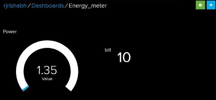
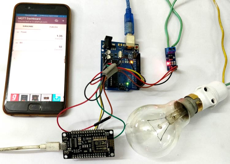
Now, upload the codes to both the boards. Connect your hardware as shown in the Circuit diagram and Open io.adafruit.com. Open the dashboard you just created. You will see the Power consumption and electricity Bill is updating.
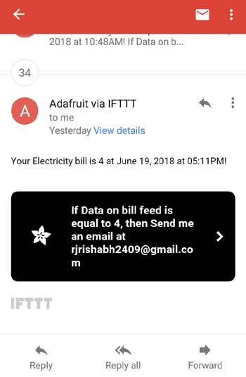
When your bill reached to INR 4 then you will get an email like this.
Android App for Monitoring Electricity Consumption:
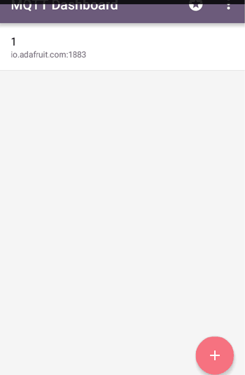
You can use Android App for monitoring the values. For this download the MQTT Dashboard android app from the Play store or from this Link.
To setup connection with the io.adafruit.com follow these steps:
Step 1: Open the App and click on “+” sign. Fill Client Id anything you want. Server and port remain same as shown in the screenshot. You will get Username and password (Active key) from the AdaFruit IO dashboard as shown below.
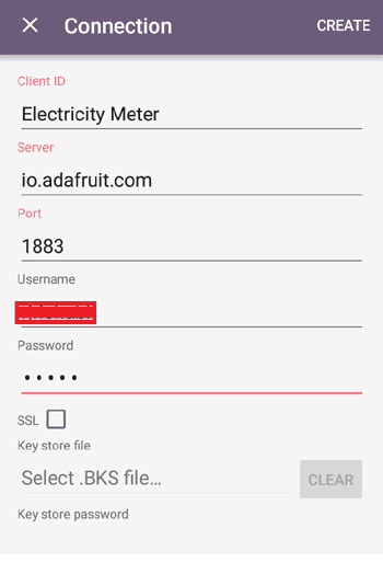
Active Key is your password.
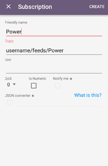
Step 2: Select Electricity Meter and select Subscribe. In subscription, give friendly name and topic. Topic format is ‘yourusername’/feeds/’feedname’ and click on create.
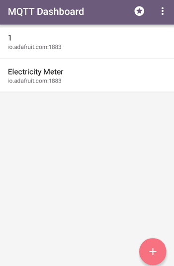
Step 3: In the same way, make subscription for bill feed.
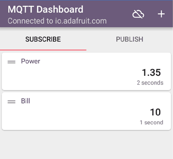
Step 4: As your appliances consuming energy, updated values will be displayed under the Power and Bill.
This is how you can create a Smart Electricity Energy Meter, which can be not only monitored from anywhere in the world but also trigger Email when you have high Electricity consumption.
Also check our all the IoT Projects.
Complete Project Code
Code For Arduino
#include "ACS712.h"

char watt[5];

ACS712 sensor(ACS712_30A, A0);

unsigned long last_time =0;

unsigned long current_time =0;

float Wh =0 ;

void setup() {

  Serial.begin(115200);

  sensor.calibrate();

}
void loop() {

  float V = 230;

  float I = sensor.getCurrentAC();

// Serial.println(I);

  float P = V * I;

  last_time = current_time;

  current_time = millis();

  Wh = Wh+  P *(( current_time -last_time) /3600000.0) ;

   dtostrf(Wh, 4, 2, watt);

Serial.write(watt);

  delay(10000);

}

Code For NodeMCU
#include <ESP8266WiFi.h>

#include "Adafruit_MQTT.h"

#include "Adafruit_MQTT_Client.h"

#define WLAN_SSID       "a*************"

#define WLAN_PASS       "*******************"

char watt[5];

#define AIO_SERVER      "io.adafruit.com"

#define AIO_SERVERPORT  1883

#define AIO_USERNAME    "rjrishabh"

#define AIO_KEY         "***********************"
WiFiClient client;

int bill_amount = 0;

unsigned int energyTariff = 8.0;

Adafruit_MQTT_Client mqtt(&client, AIO_SERVER, AIO_SERVERPORT, AIO_USERNAME, AIO_KEY);

Adafruit_MQTT_Publish Power = Adafruit_MQTT_Publish(&mqtt, AIO_USERNAME "/feeds/Power");

Adafruit_MQTT_Publish bill = Adafruit_MQTT_Publish(&mqtt, AIO_USERNAME "/feeds/bill");

void MQTT_connect();
void setup() {

  Serial.begin(115200);

  delay(10);

  Serial.println(F("Adafruit MQTT demo"));
  // Connect to WiFi access point.

  Serial.println(); Serial.println();

  Serial.print("Connecting to ");

  Serial.println(WLAN_SSID);
  WiFi.begin(WLAN_SSID, WLAN_PASS);

  while (WiFi.status() != WL_CONNECTED) {

    delay(500);

    Serial.print(".");

  }

  Serial.println();
  Serial.println("WiFi connected");

  Serial.println("IP address: "); Serial.println(WiFi.localIP());

}

void loop() {

  // Ensure the connection to the MQTT server is alive (this will make the first

  // connection and automatically reconnect when disconnected).  See the MQTT_connect

  // function definition further below.

  MQTT_connect();
 int i=0;

 float watt1;

 if(Serial.available() > 0 ){

   delay(100); //allows all serial sent to be received together

    while(Serial.available() && i<5) {

     watt[i++] = Serial.read();

    }

    watt[i++]='\0';

  }
 watt1 = atof(watt);

  bill_amount = watt1 * (energyTariff/1000);      // 1unit = 1kwH

  Serial.print(F("\nSending Power val "));

  Serial.println(watt1);

  Serial.print("...");
  if (! Power.publish(watt1)) {

    Serial.println(F("Failed"));

  } else {

    Serial.println(F("OK!"));

  }
   if (! bill.publish(bill_amount)) {

    Serial.println(F("Failed"));

  } else {

    Serial.println(F("OK!"));

  }
if (bill_amount==4){

for (int i =0; i<=2; i++)

{

  bill.publish(bill_amount);

delay(5000);

}

bill_amount =6;

}


delay(5000);

}
// Function to connect and reconnect as necessary to the MQTT server.

// Should be called in the loop function and it will take care if connecting.

void MQTT_connect() {

  int8_t ret;
  // Stop if already connected.

  if (mqtt.connected()) {

    return;

  }
  Serial.print("Connecting to MQTT... ");
  uint8_t retries = 3;

  while ((ret = mqtt.connect()) != 0) { // connect will return 0 for connected

       Serial.println(mqtt.connectErrorString(ret));

       Serial.println("Retrying MQTT connection in 5 seconds...");

       mqtt.disconnect();

       delay(5000);  // wait 5 seconds

       retries--;

       if (retries == 0) {

         // basically die and wait for WDT to reset me

         while (1);

       }

  }

  Serial.println("MQTT Connected!");

}
Comments
Thanks for the great content, can you please tell the value of resistor
do we need a voltage regulator for the circuit?
It depends on what you are powering the circuit with. If you are using the USB port or the DC jack then regulator circuit is not needed. The Arduino it self has an on-board regulator IC AMS1117
What are the values of resisitors?
in above circuit is the voltage divider necessary and if so what are the value of resistors?
It is safe to use one. Use 2K and 1K. when you have doubts use the calculators
https://circuitdigest.com/calculators/voltage-divider-calculator
i have a 2.2k resistor instead of 2k.when i kept the value of r1=1k and r2=2.2k it gave me a vout of 3.4375 as the input voltage was 5v.and in the above circuit description the node mcu takes upto 3.3v.so is it safe if i use the resistor combination i have for creating voltage divider?
please let me know if u are done with the project
Can u suggest the code for storage of last electricity consumption value even if the setup is power off and generating the bill by using last and current value.
Hello! My preocupation is to the level of the MQTT Dashboard android app. I don't find the same version that is used in the tutoriel. the others version seem me complicated. Thank you ...
the values are not getting updated on adafruit dashboard.i also checked it in the mqtt android app and it does no get updated.it just shows N/A.
how to calculate energy tariff?please help
Unable to get correct data at NodeMCU side, it is always showing 0.0.
Anybody who have done this project please share the sketch for same.
MailId-rakupa.rajesh@gmail.com
I have the same problem, it is always at 0.0. please email me olej_1118@yahoo.com if anyone has the solution for this problem
Have u completed the project?
If u completed please let me know, i need your guidance.
Thank you!
Hey guys, I have the same problem. Have you been able to resolve it?
did you solve the problem?
Can anybody help me, I carefully assemble the circuit but the mobile app and the MQTT dashboard is always at 0.0 and never move. please contact me olej_1118@yahoo.com. I will really appreciate your help. Thank you in advance
Please share the exact working circuit diagram. Tell me whether there is a need for a transformer or not.
Please its not updating on adafruit io dashboard how to do it please help me
For creating block of "Bill" on dashboard, do we have to use "Text" block type?
I have successfully completed this project if any one have any doubt regarding this project
ping me to maratisrikanth@gmail.com
Thanks...
Hi. I have completed this project. If you need any help I will try to help as much as I can. WhatsApp me @ +923339078239 or DM me @yebikkgayeehaigormint on Instagram. :)
hai, if i want to use this to calculate water bill, can i still used this coding but change the formula?
hello sir, this is vignesh and i am the regular visitor of your website and i love to make new projects and to learn new things from them, so basically i created this iot based power meter project and almost completed it but now stuck on adafruit io feed not working , mqqtt dashboard app showing error msg and ifttt ,it would be very helpful of you if you just tell me the steps of adafruit io and dashboard ,my mail id is rvighanesh@gmail.com, as i am new with iot and adafruit io feeds so i am having least knowlege about it ,so i look forward for ur help tahnk you..
Required android app mqtt dashboard link.. above mention link not recognize my playstore.
i am working on this project but have problem
UNO gives me good values, but nodemcu cant show the same values, i dont know why
please help
Hi, I have a question. If I manage to get the output, which is the power consumption of the light bulb, how can I ensure that the output is correct? How to check? Is it simply using the multimeter?
My power value is getting updated in adafruit dashboard, but bill is not displaying. it shows 0. please help
Can anyone tell me why bill and power is 0 and not updating..if anyone resolve,email me satshiv471@gmail.com
If anyone need help abt this project.. I'll help. I made it completely..
Getting 0 value on the Dashboard
could you please help me
Thanks
If anyone need help abt this project.. I'll help. I made it completely..email me satshiv471@gmail.com

can you tell me the wifi receiving range of nodemcu esp8266?