
In this project, we are going to make a TRIAC dimmer circuit for AC Appliances. Here we are not going to use a microcontroller. We have used basic components to complete this task. In this project, we will use Triac to control the brightness of the AC bulb with a IR TV Remote. You can also control Fan speed with your TV remote using this Triac Dimmer circuit.
For controlling current in one direction we have diodes, thyristor which can be triggered or biased in one direction at a time. Or we can say like they can be conducted only during one half cycles either positive half cycle or negative half cycle. But while working with AC we need more efficient switching devices and here TRIAC comes into picture.
If we connect two Thyristors back to bake then it becomes the TRIAC equivalent circuit. So TRIAC is also based on the same concept which can conduct during positive as well as negative half cycle of the AC sine wave. TRIAC is short form of Triode AC Switch.
Components Required:
- TSOP1738 -1
- 555 timer IC -2
- CD4017 -1
- MCT2E optocoupler -1
- MOC3021 TRIAC Driver -1
- LM7805 -1
- BC547 Transistor -1
- 12-0-12 Transformer -1
- 1n4007 Diode -10
- Capacitor 1000uF, 1uF, 4.7uF, 0.01uF, 0.1uF (4)
- Resistor 10K (2), 1k (3), 220k, 22k, 15k, 3.3k, 220ohm, 680, 330 (3)
- Resistor 30k (10k+10k+10k)
- LED -2
Circuit Diagram and Working Explanation:

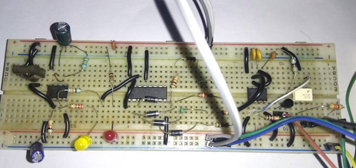
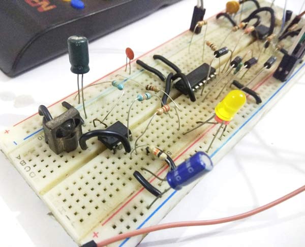
This Triac Dimmer Circuit Diagram is little bit complex for beginners but overall it's easy. In this, we have TSOP1738 IR receiver U1 which is responsible for recieving the IR signals (Infrared) from TV remote control. Lear more about Detecting IR signal with TSOP1738 here.
Once it gets a signal from TV remote, it will trigger the 555 timer U2, configured in monostable Multivibrator mode. This Multivibrator is used for generating a single pulse every time when we press any of button on the remote control. Generally when we press any button on IR remote control then it will send a train of pulses and here we do not need that train of pulse, we only need a single pulse to trigger Monostable Multivibrator and decade counter IC 4017 (U3) as well. U3 is a decade counter IC 4017, which is here used for changing the Time Period of next 555 timer IC in Monostable Multivibrator (U4) by changing its Timing Resistor value. See the circuit diagram for understanding. Here 555 IC U4 is used for generating a metric trigger pulse. Check more circuits of IC 4017 to learn more about it.
Decade counter 4017 sets the Timing Resistance (R) for the 555 IC U4 in Monostable Multivibrator by switching its output to next output pin. Here we have connected 4 different resistors to the different output pins of 4017. With the help of capacitor and the selected resistance (R5, R6, R7, R8), U4 multivibrator generates an output pulse at its output pin for fixed time period, whenever trigger pin goes low. U4 Multivibrator trigger pin will wait for zero crossing pulse coming from M2CTE optocoupler (U5) which is driven by a full bridge rectifier for detecting zero crossing. The output of U4 Monostable Multivibrator goes to Triac Driver Optocoupler MOC3021 (U7) which is responsible for controling the TRIAC by applying a pulse to gate pin of TRIAC.


A 12-0-12 AC transformer is used for giving power to circuit and for getting sine signal to find zero crossing. A 7805 voltage regulator is also used to supply regulated 5v to the circuit. LED D1 is used for indication of the remote pulse received and D8 LED is used for power indication.
Calculations for IR Remote controlled Triac Dimmer Circuit:
Monostable Multivibrator output pulse duration calculation:
Time Period = 11. * R * C

Where R is resistance and C is capacitance
Let take an example here in our circuit, we have used two monostable multivibrators. In the first 555 multivibrator we have R2 and C2:
R2= 220K
C2= 1uF
Output Pulse Time Period = (1.1 * 220 * 1000 * 1) / 1000000
Output Pulse Time Period = 0.242 S or 242 milliseconds
Now for second 555 Monostable multivibrator, below are the calculations with four different resistances, activated by pressing the remote button to control the brightness of the AC bulb:
R5 = 30K
C3+C4 = 0.1+0.1uF = 0.2uF
Output Pulse Time Period when trigger pulse trigger the multivibrator will be:
Output Pulse Time Period = (1.1 * 30 * 1000 * 0.2) / 1000000 = 0.0066 Sec or  ~7 ms (1/3 Power)
Then we have
R6 = 22K
C3+C4 = 0.1+0.1uF = 0.2uF
Output Pulse Time Period = (1.1 * 22 * 1000 * 0.2) / 1000000 = 0.00484 Sec or ~5 ms (1/2 Power)
Then we have
R7 = 15K
C3+C4 = 0.1+0.1uF = 0.2uF
Output Pulse Time Period = (1.1 * 15 * 1000 * 0.2) / 1000000 = 0.0033 Sec or ~3 ms ( 2/3 Power)
Now we have
R7 = 1K
C3+C4 = 0.1+0.1uF = 0.2uF
Output Pulse Time Period = (1.1 * 1 * 1000 * 0.2) / 1000000 = 0.00022 Sec or   <1 ms (Full Power)
Finally, the user needs to generate 0-10 ms pulse for Triac Driver to control the brightness of the AC bulb. And to generate the pulse of different time duration, user can change the R5, R6, R7, R8 values by pressing the IR remote control buttons. And also user can change the first multivibrator resistance (R2) to change remote pulse duration.
Also check the Demonstration Video given below.
Comments
this project is indeed excellent, would you mind moving it to EasyEDA?
Here the control action works only for few minutes that is once we press button to regulate the brightness and then stop for some seconds then controlling action doesn't work . means we cannot change the brightness any time we want once pressed. Help me
its not working bro
this project is not working , some give a suggestion.
This circuit works properly and reliably gives output I have prepared it and it gives nice results and somewhere you need to simply some steps and customise it properly . look at moc3021 u get a 220 v supply be cautious and cover it with acrylic box.
Hope it helps.
when i switched on main ac supply it automatically on the bulb. i just want to stop the bulb when ac supply is switched on untill press any button of ir remote. what's the solution?

it is a good project.it uses various techniques for this design.
do this plan can become commercial?