

Creating a Local Network to share personnel and confidential data's has become almost impossible for a common man in our modern world. This is mainly because all common chat methods like Whatsapp, Facebook, Hangout and almost everything involves an internet connection.
What if, we could share data without the medium of Internet?
How cool it would be if you could communicate with people inside your home or work place without a net pack or Internet Connection?
What if we could customize our chat-screen with our own imaginations?
All this is possible with a microcontroller and a Wireless transmission medium. This Arduino Chat Room using nRF24L01 Project will guide you on setting up a low cost Chat Room in your local area.
So let's jump in and see how it works.
Working Explanation:
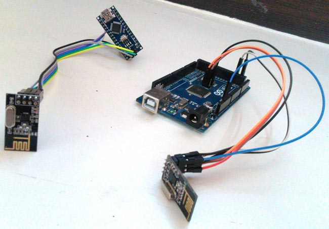
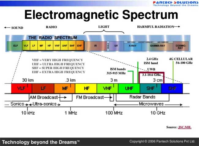
Basically to make this thing work we will need a pair of Arduino boards and cheap wireless modules. The wireless modules that we will be using here are nRF24L01. The reason for choosing these modules is that these are the successors of Zigbee and is easy to work with a set up connection. Also these modules work on 2.4 GHz(ISM band) with frequency hopping spread spectrum and shock burst options which makes us feel relaxed of interference problems. You can also check out our Arduino nRF24L01 interfacing tutorial to understand the basics of nrf24l01 module and how it works with Arduino.
Our Arduino and NRF24L01 are connected together to establish a Serial communication so that they could talk to each other. The NRF24L01 are half duplex transceiver modules, hence they can send and receive data. The data is collected from the user and transmitted this data can be received by any (or one particular) modules and display it on their screen.
But!!!!! Are we going to chat using the Debug screen of Arduino? Of course not. We are going to built and customize our own chat screen with help of ‘Processing’. Processing is a software which is capable of communicating with the Arduino using UART. We will create a .exe file with Processing language, which could run on any computer with Java Runtime. In order to Chat we just have to plug in our Arduino and open this .exe file, and Booooom!! we are into our own Privatized totally free chat-Room.
This project is limited to just adding two members to the Chat room, But the nRF24L01 has 6 Pipelines, and so there could be a maximum of 6 members in our chat room. This char room can work within the 100 meter range depending upon the nRF24L01 Modules.
So let's go shopping!!!!
Components Required:
- Arduino (any version or model) - 2Nos
- nRF24L01+ Wireless Transceiver Module - 2Nos
- 3.3 Voltage Regulator - 2Nos. (Not mandatory)
- Connecting wires
- Interest (Lolz)
Circuit Diagram:
Arduino Mega with nRF24L01:

Arduino Nano with nRF24L01:

Our project does not involve any complex connections. I have used an Arduino Mega and an Arduino Nano and their connections with nRF24L01 are shown above. You can use any Arduino Models.
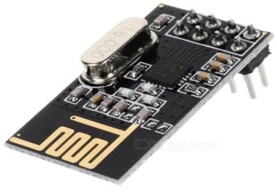
Working with nRF24L01+ Wireless Transceiver Module:
However in order to make our nRF24L01 to work free from noise we might want to consider the following things. I have been working on this nRF24L01+ for a long time and learnt the following points can help you from getting hit on a wall.
1. Most of the nRF24L01+ modules in the market are fake. The cheap ones that we can find on Ebay and Amazon are the worst (Don’t worry, with few tweaks we can make them work)
2. The main problem is the power supply not your code. Most of the codes online will work properly, I myself have a working code which I personally tested, Let me know if you need them.
3. Pay attention because the modules which are printed as NRF24L01+ are actually Si24Ri (Yes a Chinese product).
4. The clone and fake modules will consume more power, hence do not develop your power circuit based on nRF24L01+ datasheet, because Si24Ri will have high current consumption about 250mA.
5. Beware of Voltage ripples and current surges, these modules are very sensitive and might easily burn up. (;-( fried up 2 modules so far)
6. Adding a couple capacitor ( 10uF and 0.1uF) across Vcc and Gnd of the module helps in making your supply pure and this works for most of the modules.
Still if you have problems report on comment section or read through this.
Programming the Arduinos:
The program for both Arduino Nano and Mega will be similar for the change in CE and CS pins. I will explain the program by splitting it into small segments.
Since the Arduino and nRF24L01 communicates through the SPI we have called for SPI library. We have also included our Maniacbug RF24 lib for our RF modules to work. Download the file from here, and add them to your IDE.
#include <SPI.h>
#include "RF24.h"
Our NRF modules are connected to pin 8 and 10 to CE and CS respectively.
RF24 myRadio (8, 10);
We create a structured data package called package. The variable text[20] will be use to transmit data on air.
struct package
{
  char  text[20]; //Text to transmit on air
};
typedef struct package Package;
Package data;
In the void setup() function, we initialize the baud rate to 9600 and setup our modules to 115 with MIN power consumption and 250KBPS speed. You can fiddle around with these values later.
void setup()
{
  Serial.begin(9600);
  delay(1000);
  //Serial.print("Setup Initialized");
  myRadio.begin();
  myRadio.setChannel(115);  //115 band above WIFI signals
  myRadio.setPALevel(RF24_PA_MIN); //MIN power low rage
  myRadio.setDataRate( RF24_250KBPS ) ;  //Minimum speed
}
The module is made to work in transmit mode if Data is received through Serial buffer, else it will be in receiver mode looking for data on air. The data from user is stored in a char Array and sent to WriteData() to transmit them.
void loop()
{

  while(Serial.available()>0) //Get values from user
  {
    val = Serial.peek();
    if(index < 19) // One less than the size of the array
      {
          inChar = Serial.read(); // Read a character
          inData[index] = inChar; // Store it
          index++; // Increment where to write next
          inData[index] = '\0'; // Null terminate the string
      }
     if (val=='#')
      {
       strcpy( data.text, inData);
        WriteData(); //Put module in Transmit mode
    while (index!=0)
      {
      inData[index] = ' ';
      index--;
      }
      }
  }
ReadData(); //Put module Receive mode
}
void WriteData() function writes the data on 0xF0F0F0F0AA address, this address is used as writing pipe on other module.
void WriteData()
{
  myRadio.stopListening(); //Stop Receiving and start transminitng
  myRadio.openWritingPipe(0xF0F0F0F066);//Sends data on this 40-bit address
  myRadio.write(&data, sizeof(data));
  delay(300);
}
void ReadData() function writes the data on 0xF0F0F0F066 this address, this address is used as reading pipe on other module.
void ReadData()
{
myRadio.openReadingPipe(1, 0xF0F0F0F0AA); //Which pipe to read, 40 bit Address
  myRadio.startListening(); //Stop Transminting and start Reveicing
  if ( myRadio.available())
  {
    while (myRadio.available())
    {
      myRadio.read( &data, sizeof(data) );
    }
    Serial.println(data.text);
  }
}
That’s it, our programming part is over. If you cannot understand few things here, check the two programs for both the Arduinos, given in the Code section below, I have added comment lines to explain things much better.

Processing Program:
‘Processing’ is open source software which is used by artists for Graphics designing. This software is used to develop software and Android applications. It is quite easy to develop and very much similar to the Android Development IDE. Hence I have shortened the explanation.
The Processing Code for both the Chat Screens is given here:
Right click on them and click on ‘Save link as..’ to download them and open them in your computer after setting up the Arduinos. You need to install 'Processing' software to open these *.pde files and then 'Run' them to open the Chat Boxes. Comment section is open for queries. The Processing sketch for transmitter and Receiver module are identical.
In the below code section the "port = new Serial(this,Serial.list()[4],9600); //Reads the 4th PORT at 9600 baudrate" is important as it decides from which port to data from.
void setup()
{
  size(510,500);
  port = new Serial(this,Serial.list()[4],9600); //Reads the 4th PORT at 9600 baudrate
  println(Serial.list());
  background(0);
}
Here I have read data from the 4th port from my Arduino.
So for Example if you have COM[5] COM[2] COM[1] COM [7] COM[19]
Then the above code will read data from COM[7].
Testing:
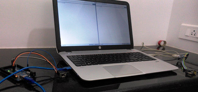
Now since our Processing and Arduino sketch is ready, just upload the program to Arduino and leave it plugged into your Laptop. Open your Processing sketch and start typing and press "Enter" your message will be transmitted to the other Arduino which will display the received text on another Processing application connected to other computer. Further check the Video below for full demonstration.
So this how you can talk to your friends and family in your local area without having any Internet connection, using this inexpensive Arduino Chat Room.
Complete Project Code
Code for Arduino Mega:

/**********
Arduino Mega with NRF24l01 for Chatroom project
Code by B.Aswinth Raj
on 8-2016
***********/

#include <SPI.h>
#include "RF24.h"  // Manicbug LIB to be downloaded
RF24 myRadio (49, 53); // CE to 49 and 53 to CS
struct package
{
  char  text[20]; //Text to transmit on air
};
//byte addresses[][6] = {"0"};
char inData[20]; // Allocate some space for the string
char inChar; // Where to store the character read
byte index = 0; // Index into array; where to store the character
 int val;
typedef struct package Package;
Package data;
void setup()
{
  Serial.begin(9600);
  delay(1000);
  //Serial.print("Setup Initialized");
  myRadio.begin();
  myRadio.setChannel(115);  //115 band above WIFI signals
  myRadio.setPALevel(RF24_PA_MIN); //MIN power low rage
  myRadio.setDataRate( RF24_250KBPS ) ;  //Minimum speed
}

void loop()
{

  while(Serial.available()>0) //Get values from user
  {
    val = Serial.peek();
    if(index < 19) // One less than the size of the array
      {
          inChar = Serial.read(); // Read a character
          inData[index] = inChar; // Store it
          index++; // Increment where to write next
          inData[index] = '\0'; // Null terminate the string
      }
     if (val=='#')
      {
       strcpy( data.text, inData);
        WriteData(); //Put module in Transmit mode
    while (index!=0)
      {
      inData[index] = ' ';
      index--;
      }
      }
  }
ReadData(); //Put module Receive mode
}
void ReadData()
{
myRadio.openReadingPipe(1, 0xF0F0F0F0AA); //Which pipe to read, 40 bit Address
  myRadio.startListening(); //Sopt Transminting and start Reveicing
  if ( myRadio.available())
  {
    while (myRadio.available())
    {
      myRadio.read( &data, sizeof(data) );
    }
  // Serial.print("\nReceived:");
    Serial.println(data.text);
  }
}

void WriteData()
{
  myRadio.stopListening(); //Stop Receiving and start transminitng
  myRadio.openWritingPipe(0xF0F0F0F066);//Sends data on this 40-bit address
  myRadio.write(&data, sizeof(data));
    //Serial.print("\nSent:");
    //Serial.println(data.msg);
  delay(300);
}

Code for Arduino Nano:
/**********
Arduino Nano with NRF24l01 for Chatroom project
Code by B.Aswinth Raj
on 8-2016
***********/

#include <SPI.h>
#include "RF24.h"  // Manicbug LIB to be downloaded
RF24 myRadio (8, 10); // CE to 8 and 10 to CS

struct package
{
  char  text[20]; //Text to transmit on air
};

typedef struct package Package;
Package data;
char inData[20]; // Allocate some space for the string
char inChar; // Where to store the character read
byte index = 0; // Index into array; where to store the character
 int val;

void setup()
{
  Serial.begin(9600);
  delay(1000);
  myRadio.begin();
  myRadio.setChannel(115);  //115 band above WIFI signals
  myRadio.setPALevel(RF24_PA_MIN); //MIN power low rage
  myRadio.setDataRate( RF24_250KBPS ) ; //Minimum speed
  //Serial.print("Setup Initialized");
}
void loop()
{
  while(Serial.available()>0) //Get values from user
  {
    val = Serial.peek();
    if(index < 19) // One less than the size of the array
      {
          inChar = Serial.read(); // Read a character
          inData[index] = inChar; // Store it
          index++; // Increment where to write next
          inData[index] = '\0'; // Null terminate the string
      }
     if (val=='#')
      {
       strcpy( data.text, inData);
        WriteData(); //Put module in Transmit mode
   while (index!=0)
      {
      inData[index] = ' ';
      index--;
      }
      }
  }
 ReadData(); //Put module Receive mode
}
void WriteData()
{
  myRadio.stopListening(); //Stop Receiving and start transminitng
  myRadio.openWritingPipe( 0xF0F0F0F0AA);  //Sends data on this 40-bit address
  myRadio.write(&data, sizeof(data));
//Serial.print("\nSent:");
//Serial.println(data.text);
  delay(300);
}
void ReadData()
{
myRadio.openReadingPipe(1, 0xF0F0F0F066); // Which pipe to read, 40 bit Address
  myRadio.startListening();  //Stop Transminting and start Reveicing
  if ( myRadio.available())
  {
    while (myRadio.available())
    {
      myRadio.read( &data, sizeof(data) );
    }
    //Serial.print("\nReceived:");
    Serial.println(data.text);
  }
}
Comments
Regarding the use of 2 arduino uno, how is it different to the example you've shown in the video?
Can you use arduino uno instead of arduino mega?
Yes Daisy you can use two Arduino UNO. The only change you have to make is change the pin numbers in the Arduino mega code similar to that of Arduino UNO
Hi, I found an error in the wire diagram for the nano. MISO and MOSI are switched from the Arduino to the nRF. Also, I was not able to get processing to display any received messages, even though they were clearly sending. Odd, because I was able to get them to send and receive in just the debug window (by terminating messages with "#").

you have shown a code for arduino nano and arduino mega but i want a program code for arduino uno.