

When we come across circuit boards which are previously designed or we take out one from old TV or computer, in attempt to repair it. And sometimes we need to know the capacitance of particular capacitor in the board to eliminate the fault. Then we face a problem in getting the exact value of capacitor from the board especially if it is a Surface Mount Device. We can buy equipment for measuring the capacitance, but all these devices are costly and not for everyone. With that in mind we are going to design a simple Arduino Capacitance Meter to measure the capacitance of unknown capacitors.
This meter can be easily made and also cost effective. We are going to make Capacitance Meter using Arduino Uno, Schmitt trigger gate and 555 IC timer.
Required Components:
- 555 timer IC
- IC 74HC14 Schmitt trigger gate or NOT gate.
- 1K Ω resistor (2 pieces), 10KΩ resistor
- 100nF capacitor, 1000µF capacitor
- 16*2 LCD,
- Breadboard and some connectors.
Circuit Explanation:
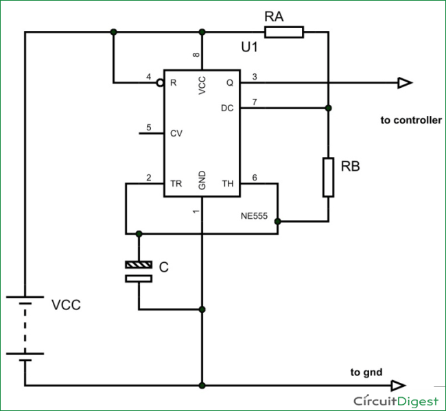
The circuit diagram of the Capacitance Meter using Arduino is shown in below figure. Circuit is simple, a LCD is interfaced with Arduino to display the measured Capacitance of capacitor. A Square wave Generator Circuit (555 in Astable mode) is connected to Arduino, where we have connected the Capacitor whose capacitance needs to be measured. A Schmitt trigger gate (IC 74LS14) is used to ensure that only rectangular wave is fed to Arduino. For filtering the noise we have added couple of capacitors across power.
This circuit can accurately measure capacitances in range 10nF to 10uF.

555 Timer IC Based Square Wave Generator:
First of all we will talk about 555 Timer IC based square wave generator, or should I say 555 Astable Multivibrator. We know that the capacitance of a capacitor cannot be measured directly in a digital circuit, in other words the UNO deals with digital signals and it cannot measure capacitance directly. So we use 555 square wave generator circuit for linking the capacitor to digital world.
Simply speaking, the timer provides square wave output whose frequency directly implicates to the capacitance connected to it. So first we get the square wave signal whose frequency is the representative of the capacitance of the unknown capacitor, and feed this signal to UNO for getting the appropriate value.
General configuration 555 in Astable mode as a shown in below figure:
The output signal frequency depends on RA, RB resistors and capacitor C. The equation is given as,
Frequency (F) = 1/ (Time period) = 1.44/ ((RA+RB*2)*C).
Here RA and RB are resistance values and C is capacitance value. By putting the resistance and capacitance values in above equation we get the frequency of output square wave.
We are going to connect 1KΩ as RA and 10KΩ as RB. So the formula becomes,
Frequency (F) = 1/ (Time period) = 1.44/ (21000*C).
By rearranging the terms we have,
Capacitance C = 1.44/ (21000*F)
In our Program Code (see below), for getting the capacitance value accurately we have calculated the result in nF by multiplying the obtained results (in farads) with “1000000000”. Also we have used ‘20800’ instead of 21000, because the accurate resistances of RA and RB are 0.98K and 9.88K.
So if we know the frequency of the square wave we can get the capacitance value.
Schmitt Trigger Gate:
The signals generated by the timer circuit are not completely safe to be directly given to the Arduino Uno. With the sensitivity of UNO in mind, we use Schmitt trigger gate. Schmitt trigger gate is a digital logic gate.
This gate provides OUTPUT based on INPUT voltage level. A Schmitt Trigger has a THERSHOLD voltage level, when the INPUT signal applied to the gate has a voltage level higher than the THRESHOLD of the logic gate, OUTPUT goes HIGH. If the INPUT voltage signal level is lower than THRESHOLD, the OUTPUT of gate will be LOW. With that we don’t usually get Schmitt trigger separately, we always have a NOT gate following the Schmitt trigger. Schmitt Trigger working is explained here: Schmitt Trigger Gate
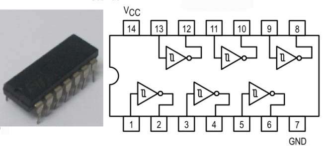
We are going to use 74HC14 chip, this chip has 6 Schmitt Trigger gates in it. These SIX gates are connected internally as shown in below figure.
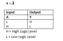
The Truth Table of Inverted Schmitt Trigger gate is show in below figure, with this we have to program the UNO for inverting the positive and negative time periods at its terminals.
We connect the signal generated by timer circuit to ST gate, we will have rectangular wave of inverted time periods at the output which is safe to be given to UNO.
Arduino measures the Capacitance:
The Uno has a special function pulseIn, which enables us to determine the positive state duration or negative state duration of a particular rectangular wave:
Htime=pulseIn(8,HIGH);
Ltime = pulseIn(8, LOW);
The pulseIn function measures the time for which High or Low level is present at PIN8 of Uno. The pulseIn function measures this High time (Htime) and Low Time (Ltime) in micro seconds. When we add Htime and Ltime together we will have the Cycle Duration, and by inverting it we will have the Frequency.
Once we have the frequency, we can get the capacitance by using the formula we discussed earlier.

Summary and Testing:
So in summary, we connect the unknown capacitor to the 555 timer circuit, which generates a square wave output whose frequency is directly related to capacitance of capacitor. This signal is given to UNO through ST gate. The UNO measures the frequency. With frequency known, we program the UNO to calculate the capacitance by using formula discussed earlier.
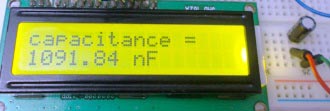
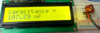
Let’s see some results I got,
When I connected 1uF Electrolytic Capacitor, the result is 1091.84 nF ~ 1uF. And the result with 0.1uF Polyester Capacitor is 107.70 nF ~ 0.1uF
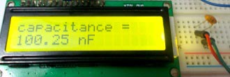
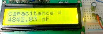
Then I connected 0.1uF Ceramic Capacitor and the result is 100.25 nF ~ 0.1uF. Also the result with 4.7uF electrolytic capacitor is 4842.83 nF ~ 4.8uF
So that is how we can simply measure the Capacitance of any capacitor.
Complete Project Code
#include <LiquidCrystal.h>
LiquidCrystal lcd(2, 3, 4, 5, 6, 7);
int32_t Htime;
int32_t Ltime;
float Ttime;
float frequency;
float capacitance;
void setup()
{
    pinMode(8,INPUT);            //pin 8 as signal input
    lcd.begin(16, 2);
    lcd.setCursor(0,0);
    lcd.print("capacitance =");
}
void loop()
{
    for (int i=0;i<5;i++)        //measure time duration five times
    {
        Ltime=(pulseIn(8,HIGH)+Ltime)/2;        //get average for each cycle
        Htime=(pulseIn(8,LOW)+Htime)/2;
    }
    Ttime = Htime+Ltime;
    frequency=1000000/Ttime;

    capacitance = (1.44*1000000000)/(20800*frequency);   //calculating the Capacitance in nF
    lcd.setCursor(0,1);
    lcd.print(capacitance);
    lcd.print(" nF   ");
    delay(500);
}
Comments
Great job! Congratulations. Helped me a lot
Great idea, but I can't figure out the for statement. When the loop starts, Htime and Ltime are both zero, so I don't know how you get an average. I must be missing something?
Htime and Ltime are never been zero, please check program again.
How small can this circuit measure.can it measure a capacitance value of 1 nF
Great work. Easy to build; works nicely.
I would point out one thing: your 1st order smoother doesn't buy you much, and the iteration buys you nothing. I would change it to something like this:
// ~~~~~~~~~~~~~~~~~~~~~~
float avgPeriod(int32_t N)
{
float Tlo = 0, Thi = 0;
for (int i = 0; i < N; i++)
{
Tlo += pulseIn(SIGNAL_PIN,LOW);
Thi += pulseIn(SIGNAL_PIN,HIGH);
}
return (float)(Thi + Tlo)/(float)N;
}
void loop()
{
const float cap_scalar = 1.443/21.077; // 1.443/(Ra+2*Rb)
float capacitance = cap_scalar*avgPeriod(25); // capacitance in nF
lcd.setCursor(0,1);
lcd.print(capacitance);
lcd.print(" nF ");
delay(500);
}
I want range 10pF to 100uF
Plz help !!
Thank you for your interesting project. Can you please explain how you calculate the range of the capacitance that the circuit can measure?

Works just fine Sir! Almost like magic..hehe. Thanks a lot Raja.