
In this project, we are going to make a Headphone/Audio Amplifier by using self-designed PCB. This project is mainly designed for amplifying the audio signal from the headphones but we can also use it for amplifying the subwoofer or speaker output, just by switching few jumpers.
When we use headphones with our audio device like mobile, laptop, FM etc, the power is sufficient for normal user but not sufficient for loud music listeners or sometimes we get very low sound from some devices. So to address this issues, we have made this handy hobby gadgets namely Headphone Amplifier. This circuit can also be used as Audio Amplifier to amplify the Subwoofer output and can be powered by a portable battery, so the user can carry it anywhere and it. Check the complete details below.
Components Required:
- IC LM386 -2
- Fabricated PCB board
- 3.5 mm Audio Jack male/female -2
- Resistor 100k -2
- Resistor 1k -1
- Resistor 22k -2
- Resistor 10R -2
- Capacitor 100nF -4
- Capacitor 10uF -4
- Capacitor 100uF -3
- Capacitor 220uF -2
- Power Supply
- LED
- Bergsticks
Working Explanation:
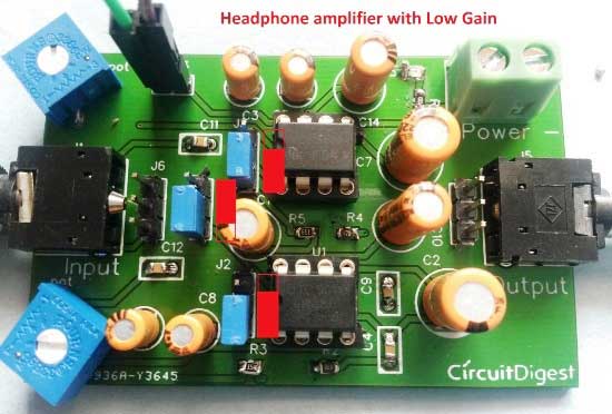
This Headphone Amplifier Circuit is made by using LM386 Audio Amplifier IC. This circuit is made in such a way that user can not only use it as Headphone Amplifier but also can drive a subwoofer speaker or normal speaker (4 ohms) and can get a amazingly loud sound through the speaker. To switch it between these two modes we have used three jumpers here. So if the user wants to drive a subwoofer speaker then he/she just needs to configure these jumpers, as we have explained below. Here we have used two LM386 and user can use 3 volts to 9 volts to drive this circuit. We have explained the jumpers configuration below in four cases, to drive the Headphone or Speaker with Low or High gain. We have used Red color rectangular symbol to denote the position of Blue jumpers, follow the red symbol to configure the jumpers:
1. To use it to amplify Headphones output, we can configure the jumpers as shown in below picture, in this case both LM386 ICs work independently for left and right speaker with low gain. User can set the volume for both the speakers of headphones independently by using two given potentiometers.
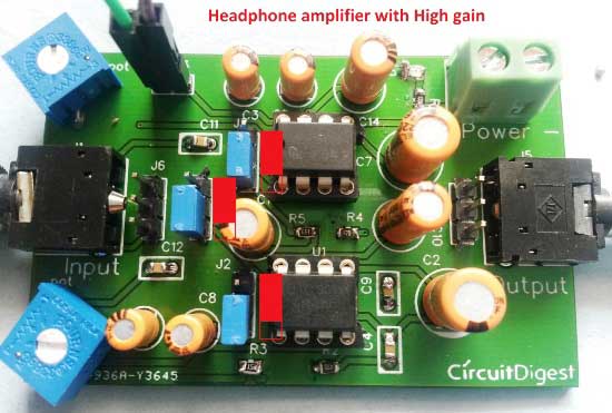
2. The second case is same as the first one (Headphone Apmlifier), only we get High gain this time. When we configure the jumpers as shown in below picture, then again both LM386 ICs work independently for left and right speaker with but with High gain this time. User can set the volume for both the speakers of headphone independently by using two given potentiometers.
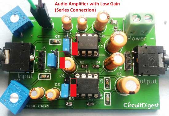
3. In the third case, we can use Subwoofer or Speaker (4 ohm/ 8-ohm speaker) by changing the position of middle jumper. When we configure the jumpers as shown in below picture, then both ICs work in series with Low gain. User can set the overall volume by using two potentiometers. You can also use headphones in this configuration but the volume should be low, otherwise in high volume headphone may damage.
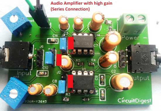
4. The fourth case is same as the third one, only we get High gain this time. We can use Subwoofer or Speaker (4 ohm/ 8-ohm speaker) in this configuration. When we configure the jumpers as shown in below picture, then both ICs work in series with High gain. User can set the overall volume by using two potentiometers. You can also use headphones in this configuration but the volume should be low, otherwise in high volume headphone may damage.
For giving audio input to this Headphone/Audio Amplifier Circuit, user need to use AUX cable, which has 3.5mm audio jack at both the side. One end will connected to this circuit and one to the audio source like mobile, laptop etc.

At the output end of this circuit, you can either use simple Headphone/earphones or can use Subwoofer or speaker. Remember to configure the jumpers accordingly as described above.
Check the demonstration Video at the end, and learn more about Audio amplifying using LM386 here. Also check Simple Audio Amplifier circuit using 555 Timer.
Circuit Diagram and PCB Layout:

You can also access the PCB layouts of this headphone amplifier here.
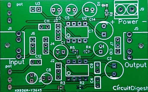
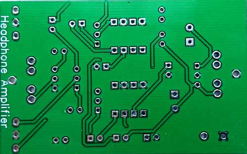
Below is the Top and Bottom layer of PCB layout:
So after few days of ordering PCB’s I got the PCB samples, shown in the below pictures:
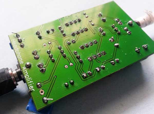
After getting these pieces, I soldered all the required components over the PCB and finally we have our Audio Amplifier Board ready:

Comments
Headphone Amplifier
its very usefull, but i cannot understand what u have in the place of U3, whats that. Reply me plzzz
They are the pins used to power the board.
The pins on the U3 are used to power the PCB. As you can see in the video we have jack for Audio in and Audio out. To power the circuit we use the green wire (positive) and black wire (ground) which is connected to the place of U3
This circuit works on 5V so
This circuit works on 5V so voltage does not matter. Use any value above 5V
Nice Tips
Thanks for explaining each and every detail of the connections with photos. I am thinking about making this as my semester project. How many Capacitors do I need to create the device? Please tell me!
I am doing engineering (thapr.edu), I think this would be a great project to display."
The components required to
The components required to build this project is already listed above
Question 2
Do you think this project can be used as a hearing aid amp. for mid hearing loss? I mean, the sound amplification is enough to cover mid range hearing loss individual? thks

its useful