

This tutorial is about Passive Low Pass Filter, a widely used term in Electronics. You will hear or use this ‘technical’ term almost every time in your studies or in your professional career. Let’s explore what is special about this technical term.
What is it, Circuit, formulas, curve?
Let’s start from the name. Do you know what is passive? What is low? What is passing and what is Filter? If you understand the meanings of those four words “Passive Low Pass Filter”, you will understand 50% of “Passive Low Pass Filter” rest of the 50% we will explore further.
“Passive”- In dictionary it means allowing or accepting what happens or what other’s do, without active response.
“Low Pass Filter”- that means passing what is low, that is also means blocking what is high. It is act as same as the traditional water filter which we have in our home/office which block impurities and only pass the clean water.
Low pass Filter pass low frequency and block higher one. A traditional low pass filter pass frequency ranging from 30-300Khz (Low Frequency) and block above that frequency if used in Audio application.
There are many things associated with a Low pass filter. As it was described before that it will filter out unwanted things (signal) of a sinusoidal signal (AC).
As passive means we generally do not apply any outer source to the filtered signal out, it can be made using passive components, which do not required power, so the filtered signal do not gate amplified, the output signal amplitude will not increase at any cost.
Low pass filters are made using resistor and capacitor combination (RC) for filtering out up to 100Khz but for the rest 100khz-300khz Resistor, Capacitor and Inductor is used (RLC).
Here is the circuit in this image:

This is a RC filter. Generally an input signal is applied to this series combination of resistor and non-polarized capacitor. It is a first order filter as there is only one reactive component in the circuitry that is capacitor. The filtered output will be available across capacitor.
What actually is happen inside the circuitry is quite interesting.
At low frequencies the reactance of the capacitor will be very large than the resistors resistive value. So, the signal’s voltage potential across capacitor will be much larger than the voltage drop across the resistor.
In higher frequencies exact opposite thing will happen. Resistor’s resistive value gets higher and due to that with the effect of capacitor’s reactance the voltage across capacitor became smaller.
Here is the curve how it’s look alike at the output of the capacitor:-

Frequency Response and Cut-Off Frequency
Let’s understand this curve further

fc is the cutoff frequency of the filter. The signal line from 0dB/118Hz to 100 KHz it is flat almost.
The formula of Calculating gain is
Gain = 20log (Vout / Vin)
If we put those values we will see the result of gain till the cut-off frequency is almost 1. 1 unit of gain or 1x gain is called as unity gain.
After the cut-off signal the response of the circuit gradually decrease to 0(Zero) and this decrement happens at a rate of -20dB/Decade. If we calculate the decrease per octave it will be -6dB. In technical terminology it is called “roll-off”.
At low frequencies capacitor’s high reactance stops the flowing of current through the capacitor.
If we apply high frequencies above the cut-off limit, the capacitor reactance decrease proportionally when signal frequency increase, resulting lower reactance the output will be 0 as the effect of short-circuit condition across capacitor.
This is the low pass filter. By selecting proper resistor and proper capacitor we could stop frequency, limit signal without affecting the signal as there is no active response.
In the above image there is a word Bandwidth. It’s signifying to which the unity gain will applied and signal will be blocked. So if it is a 150 Khz low pass filter then the bandwidth will be 150Khz. After that bandwidth frequency the signal will attenuate and stop from passing through the circuitry.
Also there is -3dB, it’s an important thing, at the cut-off frequency we will get -3dB gain where the signal attenuated to 70.7% and the capacitive reactance and resistance is equal R= Xc.
What is the formula of Cut-off Frequency?
fc = 1 / 2πRC
So, R is resistance and C is capacitance. If we put the value we will know the cutoff frequency.
Output Voltage Calculation
Let’s see the first image the circuitry where 1 resistor and one capacitor are used to form a low pass filter or RC circuit.
When DC signal applied across the circuit it’s resistance of the circuit which creates drop when current is flowing, but in case of an AC signal it’s impedance, which measured in Ohms too.
In the RC circuit there are two resistive things. One is resistance and other one is the capacitive reactance of the capacitor. So, we need to measure the capacitive reactance of the capacitor first as it will needed to calculating impedance of the circuitry.
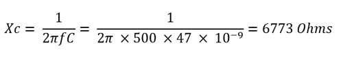
First resistive opposition is capacitive reactance, the formula is:-
Xc = 1 / 2πfc
The output of the formula will be in Ohms, as Ohms is the unit of capacitive reactance, because it is an opposition means Resistance.
The Second opposition is the resistor itself. Value of resistor is also a resistance.
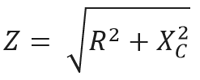
So, combining this two opposition we will get the total resistance, which is impedance in RC (AC signal input) circuit.
Impedance denotes as Z.
The RC filter act as “frequency dependent variable potential divider” circuit.
The output voltage of this divider is as follows=
Vout = Vin * (R2 / R1+R2)
R1 + R2 = RT
R1 + R2 are the total resistance of the circuit and this is the same as impedance.
So, combining this total equation we will get
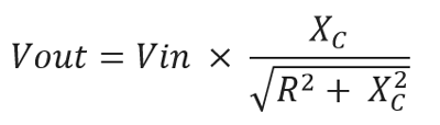
By, solving the above formula we get the final one:-
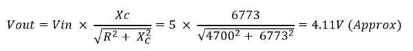
Vout = Vin * (Xc / Z)
Example with Calculation
As we already know what actually happening inside the circuit and How to find out the value. Let’s choose practical values.
Let’s pick up most common value in resistor and capacitor, 4.7k and 47nF. We selected the value as it is widely available and it is easier to calculate. Let’s see what will be the cut-off frequency and Output voltage.
Cut off Frequency will be:-
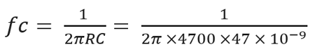
By solving this equation the cut-off frequency is 720Hz.
Let’s where it is true or not…
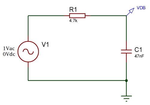
This is the circuit. As the frequency response described before that at the cut-off frequency the dB will be -3dB, Irrespective of the frequencies. We will search -3dB at the output signal and see whether it is 720Hz or not. Here is the frequency response:-

As you can see the Frequency response (Also called as Bode Plot) we set the cursor at -3dB (Red Arrow) and get 720Hz(Green Arrow) corner or Bandwidth Frequency.
If we apply 500Hz signal then the capacitive reactance will be
Then the Vout is when applied 5V Vin at 500Hz:-

Phase Shift
 out of phase at -3dB or Cut-Off frequency.
Why?
When the input voltage changes the charge time of the capacitor and due to that scenario output voltage lags behind that of the input signal or sinusoidal.
The relationship as follows:-
Input frequency increase = out of phase margin increase. This entire two are proportional to each other.
The formula of Phase shift is
Phase shift φ = -arctan (2πfRC)
Let’s see the phase shift of the circuit

This is the phase shift curve. We set the cursor at -45 (Red Arrow) and get the result of the cut-off frequency 720Hz (Green Arrow).
Time constant
As we already learn before about phase shift and frequency response, the capacitor gets a charging and discharging effect from the input signal frequencies. This charging and discharging effect is Time Constant denotes as τ (Tau). It is also related with the cut-off frequency.
How?
τ = RC = 1 / 2πfc
Sometimes we need to know the cut-off frequency when we have the time constant value in such case altering the formula we can easily get that:-
fc = 1 / 2πRC
Where RC = τ
fc = 1 / 2πτ
Due to this Time constant RC filter produce saw tooth wave, triangular wave if we change the input signal from sine wave to square wave. This is called as Integrator circuit.
Second Order Low Pass Filter: Formulas, Calculations and Frequency Curves
When a two first order low pass RC stage circuit cascaded together it is called as second order filter as there are two RC stage networks.
Here is the circuit:-

This is a second order Low Pass Filter. R1 C1 is first order and R2 C2 is second order. Cascading together they form a second order low pass filter.
Second order filter has a role of slope of 2 x -20dB/decade or -40dB (-12dB/octave).
Here is the response curve:-
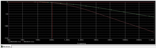
The cursor showing -3dB cut-off point in Green signal which is across the first order (R1 C1), the slope at this was seen previously -20dB/ Decade and the red one at the final output which has a slope of -40dB/Decade.
Formulas are:-
Gain at fc :-
This will calculate the gain of the second-order low pass circuit.
Cut-off frequency:-
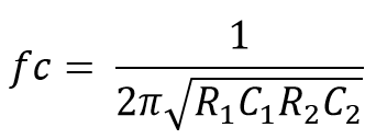
In practical the roll-off slope increase as per adding filter stage, the -3dB point and the pass band frequency changes from its actual calculated value above by a determined amount.
This determined amount is calculated by the following equation:-
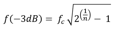
It’s not so good to cascade two passive filters as dynamic impedance of each filter order effects other network in same circuitry.
Applications
Low pass filter is widely used circuit in electronics.
Here are few applications:-
- Audio receiver and Equalizer
- Camera filter
- Oscilloscope
- Music control system and Bass frequency modulation
- Function Generator
- Power Supply

this is educative