

A Line Follower Robot is a simple yet fascinating robot for most students/hobbyists to build. In this tutorial we will learn How a Line Follower Robot Works and how we can build one using the PIC Microcontroller PIC16F877A. PIC16F877A is a 40-pin Multipurpose MCU from Microchip, we have used this IC in our complete PIC tutorial series. If you are new, here you might want to a look at these PIC tutorials to learn the basic of this IC and how to upload programs to the microcontroller. Since we have already covered this information in our tutorials we will skip them in the explanation below.
If you are interested in robotics then you should be very familiar with the name “Line Follower Robot”. This robot is capable of following a line, just by using pair of sensor and motors. This robot gives you room for infinite development and robots like Kiva (Amazon warehouse robot) are an example for this. You can also check our other Line Follower Robots:
- Line Follower Robot using 8051 Microcontroller
- Line Follower Robot using Arduino
- Line Follower Robot using Raspberry Pi
Materials Required:
- PIC16F877A
- IR Sensor (2Nos)
- DC Gear Motor (2Nos)
- L293D Motor Driver
- Chaises (You can also build your own using cardboards)
- Power bank (Any available power source)
Concepts of Line Follower
Line Follower Robot is able to track a line with the help of an IR sensor. This sensor has a IR Transmitter and IR receiver. The IR transmitter (IR LED) transmits the light and the Receiver (Photodiode) waits for the transmitted light to return back. An IR light will return back only if it is reflect by a surface. Whereas, all surfaces do not reflect an IR light, only white the colour surface can completely reflect them and black colour surface will completely observe them as shown in the figure below. Learn more about IR sensor module here.

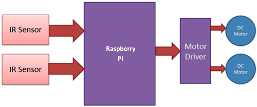
Now we will use two IR sensors to check if the robot is in track with the line and two motors to correct the robot if its moves out of the track. These motors require high current and should be bi-directional; hence we use a motor driver module like L293D. We will also need a Microcontroller like PIC to instruct the motors based on the values from the IR sensor. A simplified block diagram of the same is shown below.
These two IR sensors will be placed one on either side of the line. If none of the sensors are detecting a black line them they PIC microcontroller instructs the motors to move forward as shown below
If left sensor comes on black line then the microcontroller instructs the robot to turn left by rotating the right wheel alone.
If right sensor comes on black line then the microcontroller instructs the robot to turn right by rotating the left wheel alone.
If both sensors comes on black line, robot stops.
This way the Robot will be able to follow the line without getting outside the track. Now let us see how the circuit and Code looks like.
Circuit Diagram and Explanation:
The complete circuit diagram for this PIC based Line Follower Robot is shown below

The circuit employs two IR sensors and a pair of DC gear motors along with a motor driver module as shown above. The Motor driver module used in this project is L293D, we will need a motor driver because the output pin of the PIC Microcontroller cannot source enough current for the motors to drive. This module will be powered directly from the power source (5V) as shown in the circuit. The module has four pins (two for each motor) which are connected to the PIC to control the direction of the motors. We also have two IR sensors which act as an input to the PIC microcontroller. These sensors will go high (1) if they are over a white surface and will go low(0) when over a black surface. The complete pin connections are illustrated in the table below.
|
S.No |
Connected from |
Connected to |
|
1 |
IR sensor Left out pin |
RD2 (pin 21) |
|
2 |
IR sensor Right out pin |
RD3 (pin 22) |
|
4 |
Motor 1 Channel A pin |
RC4 (pin 23) |
|
5 |
Motor 1 Channel B pin |
RC5 (pin 25) |
|
6 |
Motor 2 Channel A pin |
RC6 (pin 26) |
|
7 |
Motor 2 Channel B pin |
RC7 (pin 27) |
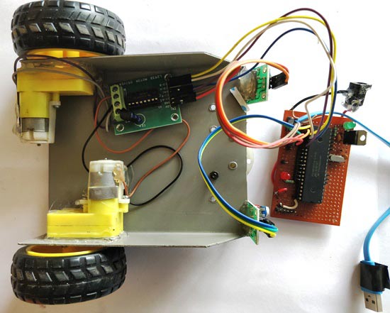
In the actual hardware I have used a power bank which will give an output of + 5V directly through its USB port; hence I have bypassed the 7805 voltage regulator and powered the PIC, sensors and Motors using the same. You can do the same of use a 12V battery along with a regulator as shown in the circuit.
Programming PIC Microcontroller:
Once you are ready with your Hardware it is time to start programming. The complete program of this PIC Line Follower Robot Project is given at the end of this page. However the important chunks are explained below.
Initialize the I/O pins by the following lines. The 2 IR sensor pins act as input and the four motor pins acts as output pins.
TRISD2 = 1; TRISD3 = 1; //Bath the IR sensor pins are declared as input
TRISC4 = 0; TRISC5 = 0; //Motor 1 pins declared as output
TRISC6 = 0; TRISC7 = 0; //Motor 2 pins declared as output
Now, we have to read the status of both the IR sensor and control the motor accordingly. For example if the both the sensors are high (does not come under black line) then we move both the motors forward as shown in the program below.
if (RD2==1 && RD3==1) //Both sensor not over balck line
         {
         RC4=0; RC5=1; //Motor 1 forward
         RC6=1; RC7=0; //Motor 2 forward
         }
If the left sensor comes over the black line then we make a right turn by holding the Motor 1 still and rotating the Motor 2 in forward direction. This type of turning is called as differential turning.
   else if (RD2==0 && RD3==1) //Left sensor is over black line
         {
         RC4=1; RC5=1; //Motor 1 stop
         RC6=1; RC7=0; //Motor 2 forward
         }
Similarly, if the right sensor comes over the black line then the bot is made to take a left turn by holding the second motor still and rotating the first motor alone in forward direction as shown below.
else if (RD2==1 && RD3==0) //Right sensor is over black line
         {
         RC4=0; RC5=1; //Motor 1 forward
         RC6=1; RC7=1; //Motor 2 stop
         }
Finally if both the sensors come under a black line then its time to stop the bot. This can be done by making all the pins of both the motors high. The code to do the same is shown below
else //Both Sensor over black line
         {
         RC4=1; RC5=1; //Motor 1 stop
         RC6=1; RC7=1; //Motor 2 stop
         }
That is it the program is ready and can be uploaded to the PIC using any programmer like PicKit.
PIC Line Follower in Action:
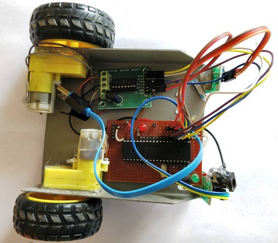
Once the hardware and code is ready, its time for some action. As said earlier I have used a Power bank to power the bot, so all I have to do is simply connect the power bank to the bot which has the hardware set up and code already uploaded.
The PIC Perf board was made for our PIC tutorial series, in which we learnt how to use PIC microcontroller. You might want to go back to those PIC Microcontroller tutorials using MPLABX and XC8 if you do not know how to burn a program using Pickit 3, since I will be skipping all those basic information.
Now, simply launch the bot over a black line and you should watch it following the line.
You might face some difficulties in the beginning in that case read further. If the wheels rotate in opposite simply interchange the polarity of the motor who’s wheel is rotating in opposite direction. If the bot deviates from the line, interchange the IR sensor and all should be good.
The complete working of the bot can be found at the video given below. Hope you like the project and enjoyed building something similar. If you have problem in getting this to work you can post them in the comment section below to get it resolved or use ours forums to discuss technical contents.
Complete Project Code
/*

Line Follower using PIC16F877A

 * Code by: B.Aswinth Raj

 * Dated: 11-09-2017

 * More details at: www.CircuitDigest.com

 */
#include <xc.h>
#pragma config FOSC = HS        // Oscillator Selection bits (HS oscillator)

#pragma config WDTE = OFF       // Watchdog Timer Enable bit (WDT disabled)

#pragma config PWRTE = ON       // Power-up Timer Enable bit (PWRT enabled)

#pragma config BOREN = ON       // Brown-out Reset Enable bit (BOR enabled)

#pragma config LVP = OFF        // Low-Voltage (Single-Supply) In-Circuit Serial Programming Enable bit (RB3 is digital I/O, HV on MCLR must be used for programming)

#pragma config CPD = OFF        // Data EEPROM Memory Code Protection bit (Data EEPROM code protection off)

#pragma config WRT = OFF        // Flash Program Memory Write Enable bits (Write protection off; all program memory may be written to by EECON control)

#pragma config CP = OFF         // Flash Program Memory Code Protection bit (Code protection off)

void main()

{

     TRISD2 = 1; TRISD3 = 1; //Bath the IR sensor pins are declared as input

     TRISC4 = 0; TRISC5 = 0; //Motor 1 pins declared as output

     TRISC6 = 0; TRISC7 = 0; //Motor 2 pins declared as output


     while(1)

         {


         if (RD2==1 && RD3==1) //Both sensor not over balck line

         {

         RC4=0; RC5=1; //Motor 1 forward

         RC6=1; RC7=0; //Motor 2 forward

         }


         else if (RD2==0 && RD3==1) //Left sensor is over black line

         {

         RC4=1; RC5=1; //Motor 1 stop

         RC6=1; RC7=0; //Motor 2 forward

         }


         else if (RD2==1 && RD3==0) //Right sensor is over black line

         {

         RC4=0; RC5=1; //Motor 1 forward

         RC6=1; RC7=1; //Motor 2 stop

         }


         else //Both Sensor over black line

         {

         RC4=1; RC5=1; //Motor 1 stop

         RC6=1; RC7=1; //Motor 2 stop

         }


         }

}
Comments
There are some components in
There are some components in the pictures but they are all missing from the circuit diagram, like that led and that resistor... If someone builds the car using the provided circuit diagram, it won't work.....

This given program is giving errors in compiling.