
CNC Machines are Computerized Numerical Control Machines which are used to draw anything or design any mechanical part according to the design program fed into their controller unit. Controller unit can be either computer or microcontroller. CNC machines have stepper and servo motors to draw the design as per the fed program.
After researching on CNC machines, I decided to build my own CNC machine using locally available materials. There are so a many CNC machines in the world, some of which are much technical and complex to make or even operate them properly. For this reason, I decided to make a simple CNC Plotter Machine based on Arduino which is by far the simplest to make. You can also use this as an Arduino CNC drawing machine with little modifications.
This DIY Arduino CNC Machine can draw most of the basic shapes, texts and even cartoons. It's operation is similar to the way a human hand writes. It’s faster and more accurate compared to the way a human being can write or draw. Check the demonstration Video at the end of this tutorial.
Building an Arduino CNC Machine:
For a CNC plotting machine to operate, 3 axes are required (x-axis, y-axis and z-axis. The x-axis and y-axis work in unison to create a 2D image on a plain paper. These x and y axis are placed 90 degrees to each other such that any point on the plain surface is defined by a given value of x and y. The z-axis is used lift and lower the pen onto the plain paper.
Depending on the image to be drawn, the computer will generate the appropriate coordinates and send them to the microcontroller through the USB port. The microcontroller interprets these coordinates and then controls the positions of the motors to create the image. Here we have used Arduino as the Microcontroller to build this CNC Machine. The three-axis movements are provided by stepper motors, which will be ocntrolled by the Arduino board. You can chec out how to interface stepper motor with Arduino if you are new to this.
So let's start building our Arduino CNC device step by step.
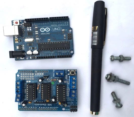
What You Need:
Note: My design is quite different in hardware in terms of size and the materials used. I wasn’t able to find old DVD drives so I opted for printer parts. Whichever you use, ensure that it has a stepper motor.
Hardware Requirement:
- Aluminium sheet (710mm x 710mm)
- Old HP/Epson printer. You can use old computer DVD drives
- Bolts and nuts
- Perspex glass
- Arduino UNO
- L293D motor driver shield or an Arduino CNC shield
- Mini servo motor
- A pen
Tools:
- Screwdriver
- Drill
- Cutting tool (hacksaw)
- Glue
- Bench device
Softwares:
For the efficient operation of this machine, the following softwares are used. Go to the various websites and download them.
- Arduino IDE version 1.6.6 or later versions from here
- Processing IDE version 3.1.1 or later version from here
- Inkscape version 0.48.5. Download it from here.
- Grbl controller (optional)
The Base for CNC Plotter Machine:
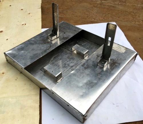
The main body of this device is the base which supports all the major parts of the machine together so that the machine is firm and is also portable. In this design we will use aluminum to construct the base since it is light, simple to bend and cut and also it gives a good shiny appearance since it doesn’t rust.
The design and dimensions of my base is shown below:
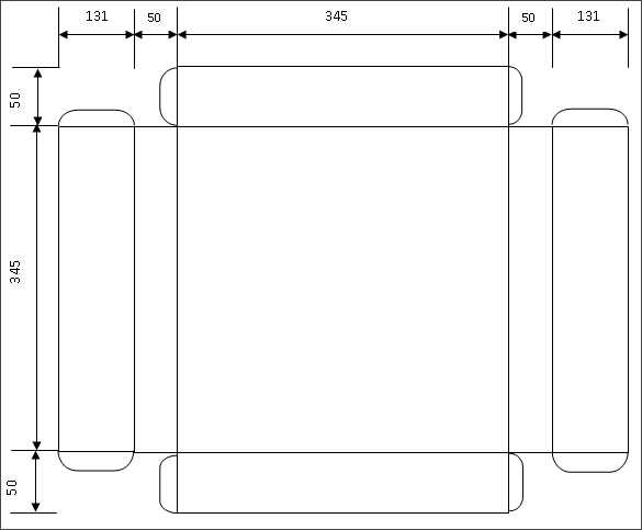
Note: All dimensions are in millimeters.
After all the bending and cutting, I was able to produce a very firm base as shown below:
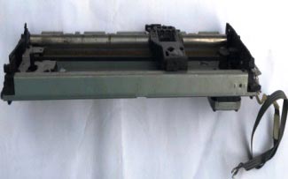
Assembly of the X, Y and Z Axes:
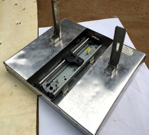
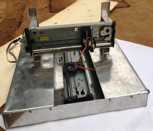
To make x and y axes, two printer cradles are used. Each of these parts contains a stepper motor and a belt drive mechanism usually used to move the cartridge to and fro.
For the z-axis, a mini servo motor is attached on the y-axis using glue. This servo motor is used to move the pen up and down. A good support mechanism should be constructed that will enable the free up and down movement of the pen.
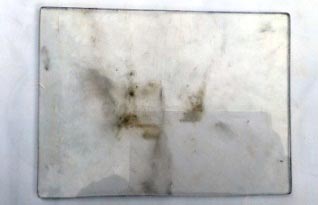
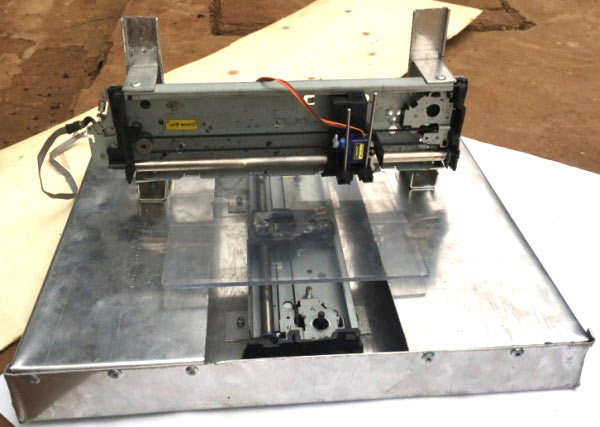
Drawing Platform for CNC Machine:
Due to the immense size of this machine, the device is capable of drawing on an A5 sized paper. Therefore we will cut out an A5 (148mmx210mm) sized platform from the Perspex glass and then stick it onto the x-axis moving part using glue.

Wiring and Circuit of CNC Machine:
Insert the L293D motor driver shield onto the Arduino UNO board. This shield can drive two stepper motors at the same time and two servo motors. Connect the two stepper motors as shown below. The ground connection should be left unconnected since the motors are bipoplar type. This will act as our Arduino CNC controller for our Plotter machine.

Also attach the mini servo motor to servo1. Connect a 7.5V - 9V power supply to the power port of the motor driver shield. The machine is now ready for testing.
Arduino CNC Machine Code and Testing:
First we need to test the stepper motors and see whether they are connected correctly.
Since we are using the L293D motor driver shield, we need to download the AFmotor Library from here. Then add it into your Arduino IDE library folder. Ensure you rename it to AFMotor. If the Arduino IDE was open close it and open it again and click on file -> examples -> Adafruit Motor Shield Library -> stepper. Ensure you choose the correct port and board in tools and then upload the code into the Arduino board. Some movements should be observed on stepper motor one.
In order to test motor two, change the motor port from 2 to 1 in the following line and then upload the code again.
#include <AFMotor.h>

// Connect a stepper motor with 48 steps per revolution (7.5 degree)
// to motor port #2 (M3 and M4)
AF_Stepper motor(48, 2);
Arduino Code for CNC Machine:
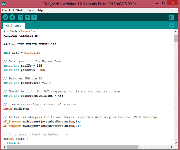
Once the stepper motors are responding appropriately, copy the Arduino code for CNC machine from the Code section below and upload it to the Arduino board. You can download the code from the below link.
G-Code for CNC Machine:
G - CODE is the language in which we tell computerized machines (CNC) to do something. It's basically a file that contains X, Y and Z coordinates.
For example:
G17 G20 G90 G94 G54
G0 Z0.25X-0.5 Y0.
Z0.1
G01 Z0. F5.
G02 X0. Y0.5 I0.5 J0. F2.5
X0.5 Y0. I0. J-0.5
X0. Y-0.5 I-0.5 J0.
X-0.5 Y0. I0. J0.5
G01 Z0.1 F5.
G00 X0. Y0. Z0.25
Writing a G-Code for just a simple square can be really challenging but luckily we have a software which can help us generate a G-Code. This software is called "Inkscape", download it from here.
You can generate your own G-Code using Inkscape, which we have explained in next section or but you can use readily available G-Codes on the internet.
Before I show you how to generate G-Codes using Inkscape lets discuss on how to send those G-Codes into the Arduino. The software that will enable us send G-Codes into the Arduino is called Processing.
Processing IDE to upload the G-Code:
This platform will help us send the G-Codes to the Arduino board. To do so, you will have to download the GCTRL.PDE file.
Download GCTRL.pde file from here and open it using Processing IDE
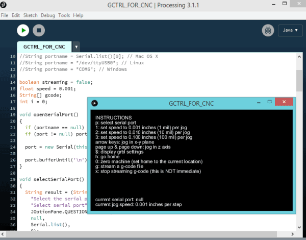
Once you’ve opened it in the Processing IDE, click run. A window appears with all the instructions. Press p on the keyboard. The system will ask you to choose a port. So select the port on which your Arduino board is connected. I my case it's port 6.
Now press g and browse to the folder where you saved your G-CODE. Select the right G-CODE and press enter. If everything was connected right, you should see you device starting to plot on the paper.
If you want to terminate the process, just press x and the device will stop whatever it was doing.
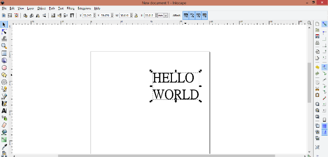
How to Generate Your Own G-Code:
We mentioned that Inkscape is the software we will use to generate our G-CODES. In this example we will create a simple text (HELLO WORLD) as shown below.
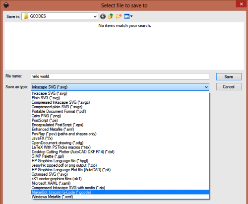
Note: Inkscape has no in built way of saving files as G-CODE. Therefore you need to install an Add-on that enables the export images to G-CODE files. Download this MakerBot Unicorn plugin from here with installation notes.
If the installation was successful, Open the Inkscape, go to File menu and click "Document Properties". First change dimensions from px to mm. Also reduce the width and height to 90 mm. Now close this window. A square appears as the drawing area. This is the area that we will use to write our text.
Now on the left side bar, click on the create and edit text object tab. Type the text "HELLO WORLD" and position it at the top right corner of the square as shown below.
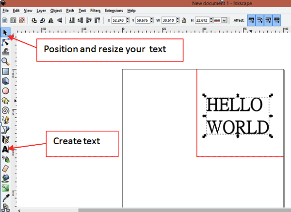
Click text and choose the type of font style that you prefer. Click apply and the close.
Now click on path and select "object to path"
Your text is now ready to be saved as G-CODE. Click on file -> save as and then type the file name as "hello world"
Change the file type to "MakerBot Unicon G-Code" as shown in below pic. This will only appear if the Add-on installation was successful. Finally click on save and click ok on the pop-up window.
You have generated a G-Code and it can be plotted using the previous procedures.
The GRBL Controller:
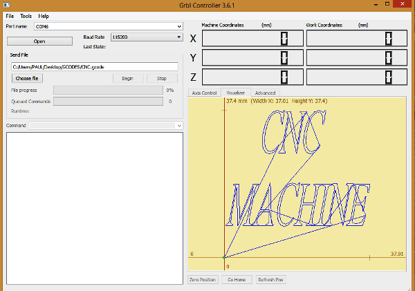
Once you’ve managed to generate a G-Code using Inkscape, it may be necessary to view the G-Code in order to ensure that it is within the drawing limits.
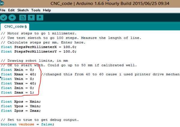
The drawing limits are set in the Arduino CNC CODE in the lines shown below:
The image as show above in the GRBL controller should not go beyond those limit as shown in the CNC Arduino code above. If it goes beyond those limit for example towards the negative side of the x-axis, that part on the negative side will not be plotted.
In this example x and y values range from 0mm to 40mm.
Since I am using printer parts which can plot on a larger area, I change the max values from 40mm to 60mm.
Whenever you generate a G-Code using Inkscape, you can first open that G-Code in the GRBL program to see whether it is within those limits. If not within, you need to resize you image in the Inkscape until it is within your limits.
So this is the cheap and simplest method to build a CNC Plotter machine using arduino uno at home. Try it out and let us know in comments also check the Video below.
Complete Project Code
/*

 Send GCODE to this Sketch using gctrl.pde https://github.com/damellis/gctrl

 Convert SVG to GCODE with MakerBot Unicorn plugin for Inkscape available here https://github.com/martymcguire/inkscape-unicorn

 Arduino code for this Mini CNC Plotter based on: https://github.com/adidax/mini_cnc_plotter_firmware

*/
#include <Servo.h>

#include <AFMotor.h>
#define LINE_BUFFER_LENGTH 512
char STEP = MICROSTEP ;
// Servo position for Up and Down

const int penZUp = 115;

const int penZDown = 83;
// Servo on PWM pin 10

const int penServoPin =10 ;
// Should be right for DVD steppers, but is not too important here

const int stepsPerRevolution = 48;
// create servo object to control a servo

Servo penServo;
// Initialize steppers for X- and Y-axis using this Arduino pins for the L293D H-bridge

AF_Stepper myStepperY(stepsPerRevolution,1);

AF_Stepper myStepperX(stepsPerRevolution,2);
/* Structures, global variables    */

struct point {

  float x;

  float y;

  float z;

};
// Current position of plothead

struct point actuatorPos;
//  Drawing settings, should be OK

float StepInc = 1;

int StepDelay = 0;

int LineDelay =0;

int penDelay = 50;
// Motor steps to go 1 millimeter.

// Use test sketch to go 100 steps. Measure the length of line.

// Calculate steps per mm. Enter here.

float StepsPerMillimeterX = 100.0;

float StepsPerMillimeterY = 100.0;
// Drawing robot limits, in mm

// OK to start with. Could go up to 50 mm if calibrated well.

float Xmin = 0;

float Xmax = 40;

float Ymin = 0;

float Ymax = 40;

float Zmin = 0;

float Zmax = 1;
float Xpos = Xmin;

float Ypos = Ymin;

float Zpos = Zmax;
// Set to true to get debug output.

boolean verbose = false;
//  Needs to interpret

//  G1 for moving

//  G4 P300 (wait 150ms)

//  M300 S30 (pen down)

//  M300 S50 (pen up)

//  Discard anything with a (

//  Discard any other command!
/**********************

 * void setup() - Initialisations

 ***********************/

void setup() {

  //  Setup


  Serial.begin( 9600 );


  penServo.attach(penServoPin);

  penServo.write(penZUp);

  delay(100);
  // Decrease if necessary

  myStepperX.setSpeed(600);

  myStepperY.setSpeed(600);


  //  Set & move to initial default position

  // TBD
  //  Notifications!!!

  Serial.println("Mini CNC Plotter alive and kicking!");

  Serial.print("X range is from ");

  Serial.print(Xmin);

  Serial.print(" to ");

  Serial.print(Xmax);

  Serial.println(" mm.");

  Serial.print("Y range is from ");

  Serial.print(Ymin);

  Serial.print(" to ");

  Serial.print(Ymax);

  Serial.println(" mm.");

}
/**********************

 * void loop() - Main loop

 ***********************/

void loop()

{


  delay(100);

  char line[ LINE_BUFFER_LENGTH ];

  char c;

  int lineIndex;

  bool lineIsComment, lineSemiColon;
  lineIndex = 0;

  lineSemiColon = false;

  lineIsComment = false;
  while (1) {
    // Serial reception - Mostly from Grbl, added semicolon support

    while ( Serial.available()>0 ) {

      c = Serial.read();

      if (( c == '\n') || (c == '\r') ) {             // End of line reached

        if ( lineIndex > 0 ) {                        // Line is complete. Then execute!

          line[ lineIndex ] = '\0';                   // Terminate string

          if (verbose) {

            Serial.print( "Received : ");

            Serial.println( line );

          }

          processIncomingLine( line, lineIndex );

          lineIndex = 0;

        }

        else {

          // Empty or comment line. Skip block.

        }

        lineIsComment = false;

        lineSemiColon = false;

        Serial.println("ok");

      }

      else {

        if ( (lineIsComment) || (lineSemiColon) ) {   // Throw away all comment characters

          if ( c == ')' )  lineIsComment = false;     // End of comment. Resume line.

        }

        else {

          if ( c <= ' ' ) {                           // Throw away whitepace and control characters

          }

          else if ( c == '/' ) {                    // Block delete not supported. Ignore character.

          }

          else if ( c == '(' ) {                    // Enable comments flag and ignore all characters until ')' or EOL.

            lineIsComment = true;

          }

          else if ( c == ';' ) {

            lineSemiColon = true;

          }

          else if ( lineIndex >= LINE_BUFFER_LENGTH-1 ) {

            Serial.println( "ERROR - lineBuffer overflow" );

            lineIsComment = false;

            lineSemiColon = false;

          }

          else if ( c >= 'a' && c <= 'z' ) {        // Upcase lowercase

            line[ lineIndex++ ] = c-'a'+'A';

          }

          else {

            line[ lineIndex++ ] = c;

          }

        }

      }

    }

  }

}
void processIncomingLine( char* line, int charNB ) {

  int currentIndex = 0;

  char buffer[ 64 ];                                 // Hope that 64 is enough for 1 parameter

  struct point newPos;
  newPos.x = 0.0;

  newPos.y = 0.0;
  //  Needs to interpret

  //  G1 for moving

  //  G4 P300 (wait 150ms)

  //  G1 X60 Y30

  //  G1 X30 Y50

  //  M300 S30 (pen down)

  //  M300 S50 (pen up)

  //  Discard anything with a (

  //  Discard any other command!
  while( currentIndex < charNB ) {

    switch ( line[ currentIndex++ ] ) {              // Select command, if any

    case 'U':

      penUp();

      break;

    case 'D':

      penDown();

      break;

    case 'G':

      buffer[0] = line[ currentIndex++ ];          // /!\ Dirty - Only works with 2 digit commands

      //      buffer[1] = line[ currentIndex++ ];

      //      buffer[2] = '\0';

      buffer[1] = '\0';
      switch ( atoi( buffer ) ){                   // Select G command

      case 0:                                   // G00 & G01 - Movement or fast movement. Same here

      case 1:

        // /!\ Dirty - Suppose that X is before Y

        char* indexX = strchr( line+currentIndex, 'X' );  // Get X/Y position in the string (if any)

        char* indexY = strchr( line+currentIndex, 'Y' );

        if ( indexY <= 0 ) {

          newPos.x = atof( indexX + 1);

          newPos.y = actuatorPos.y;

        }

        else if ( indexX <= 0 ) {

          newPos.y = atof( indexY + 1);

          newPos.x = actuatorPos.x;

        }

        else {

          newPos.y = atof( indexY + 1);

          indexY = '\0';

          newPos.x = atof( indexX + 1);

        }

        drawLine(newPos.x, newPos.y );

        //        Serial.println("ok");

        actuatorPos.x = newPos.x;

        actuatorPos.y = newPos.y;

        break;

      }

      break;

    case 'M':

      buffer[0] = line[ currentIndex++ ];        // /!\ Dirty - Only works with 3 digit commands

      buffer[1] = line[ currentIndex++ ];

      buffer[2] = line[ currentIndex++ ];

      buffer[3] = '\0';

      switch ( atoi( buffer ) ){

      case 300:

        {

          char* indexS = strchr( line+currentIndex, 'S' );

          float Spos = atof( indexS + 1);

          //         Serial.println("ok");

          if (Spos == 30) {

            penDown();

          }

          if (Spos == 50) {

            penUp();

          }

          break;

        }

      case 114:                                // M114 - Repport position

        Serial.print( "Absolute position : X = " );

        Serial.print( actuatorPos.x );

        Serial.print( "  -  Y = " );

        Serial.println( actuatorPos.y );

        break;

      default:

        Serial.print( "Command not recognized : M");

        Serial.println( buffer );

      }

    }

  }

}
/*********************************

 * Draw a line from (x0;y0) to (x1;y1).

 * int (x1;y1) : Starting coordinates

 * int (x2;y2) : Ending coordinates

 **********************************/

void drawLine(float x1, float y1) {
  if (verbose)

  {

    Serial.print("fx1, fy1: ");

    Serial.print(x1);

    Serial.print(",");

    Serial.print(y1);

    Serial.println("");

  }
  //  Bring instructions within limits

  if (x1 >= Xmax) {

    x1 = Xmax;

  }

  if (x1 <= Xmin) {

    x1 = Xmin;

  }

  if (y1 >= Ymax) {

    y1 = Ymax;

  }

  if (y1 <= Ymin) {

    y1 = Ymin;

  }
  if (verbose)

  {

    Serial.print("Xpos, Ypos: ");

    Serial.print(Xpos);

    Serial.print(",");

    Serial.print(Ypos);

    Serial.println("");

  }
  if (verbose)

  {

    Serial.print("x1, y1: ");

    Serial.print(x1);

    Serial.print(",");

    Serial.print(y1);

    Serial.println("");

  }
  //  Convert coordinates to steps

  x1 = (int)(x1*StepsPerMillimeterX);

  y1 = (int)(y1*StepsPerMillimeterY);

  float x0 = Xpos;

  float y0 = Ypos;
  //  Let's find out the change for the coordinates

  long dx = abs(x1-x0);

  long dy = abs(y1-y0);

  int sx = x0<x1 ? StepInc : -StepInc;

  int sy = y0<y1 ? StepInc : -StepInc;
  long i;

  long over = 0;
  if (dx > dy) {

    for (i=0; i<dx; ++i) {

      myStepperX.onestep(sx,STEP);

      over+=dy;

      if (over>=dx) {

        over-=dx;

        myStepperY.onestep(sy,STEP);

      }

    delay(StepDelay);

    }

  }

  else {

    for (i=0; i<dy; ++i) {

      myStepperY.onestep(sy,STEP);

      over+=dx;

      if (over>=dy) {

        over-=dy;

        myStepperX.onestep(sx,STEP);

      }

      delay(StepDelay);

    }

  }
  if (verbose)

  {

    Serial.print("dx, dy:");

    Serial.print(dx);

    Serial.print(",");

    Serial.print(dy);

    Serial.println("");

  }
  if (verbose)

  {

    Serial.print("Going to (");

    Serial.print(x0);

    Serial.print(",");

    Serial.print(y0);

    Serial.println(")");

  }
  //  Delay before any next lines are submitted

  delay(LineDelay);

  //  Update the positions

  Xpos = x1;

  Ypos = y1;

}
//  Raises pen

void penUp() {

  penServo.write(penZUp);

  delay(penDelay);

  Zpos=Zmax;

  digitalWrite(15, LOW);

    digitalWrite(16, HIGH);

  if (verbose) {

    Serial.println("Pen up!");


  }

}

//  Lowers pen

void penDown() {

  penServo.write(penZDown);

  delay(penDelay);

  Zpos=Zmin;

  digitalWrite(15, HIGH);

    digitalWrite(16, LOW);

  if (verbose) {

    Serial.println("Pen down.");

  }

}
Comments
Hello
now the file is installed but now when i save the file as G-Code some new window appears
1:MakerBot Unicorn G-Code Output (when click to ok another window appear)
2: inside in this window a heading appear"Inkscape has received additional data from the script executed. The script did not return an error, but this may indicate the results will not be as expected."
what should have to do now
help!
you can delete my previous comment.
sir i will have an error (error exit status 1)so please help me to find this error
can you help me this project ? I want to make cnc plotter and I need help please
Hi,
I assembled one of this...when I generate GCODE by inkscape there are 2 problems that make the equipment not work. The G4 commands (wait) and I need to replace the servo commands to M3S90 (pen up) and M3S68 (pen down). If I edit them manually my gcode works fine, but when I use the original inkscape gcode the GRBL stops and show a warning of error or buffer too small...could u help me????
I have realised a similar material and y have the same problem ; all others publications on the same subject have this problem Inscape
dont give the Mcodes necessary for moving the pen and y never find an other program for this necessity . For my the solution is the modification of
of the program given with part of other programs concerning CNC ; if sombody have a solution think you
;
could you please provide a detail design diagram of the model
Sir
Pls help to to step by step process to execute the software system to start this machine
hi everyone i am subha. i try to make this project. servo motor is working, Y axis also but X axis is not. I was send a g code by g code sender, then Y axis is working. servo also but X axis is not. how can i do this, pls. help me.
thanks
subha
Thank you so much it was really helpful. I just have a problem; when I upload the main cnc code on arduino my servo motor starts rotating 360 degree non-stop and I can't find the problem. I also changed the penZup and down variables but nothing changed. Can you help me figure it out please?!
Please provide the detailed diagram of frame. I could not understand cutting of frame and bending of corners. Thanks allot.
Hii sir, myself Prasad, im working on same project, i salvaged same motor from epson printer but i dont know the motor voltage, please tell me how much voltage you gave to the motor ?
Thanks.
Dear Sir, I have seen your video, it is helpful. I am trying to build a cnc writting machine. But I don't know how to send the gcode to arduino Uno. Pl help me. What softwares(version) are required and where they have to placed. Pl give me step by step guide lines. I am confused. How are arduino code are related with gcode for plotting in cnc writting machine. Pl help. I will be grateful. Thanks . B. Sanyal
can i get the circuit diagram?
Can I ask what the printer model is?(printer cardles)

please, the circuit diagram arduino, stepper motors and servo?