
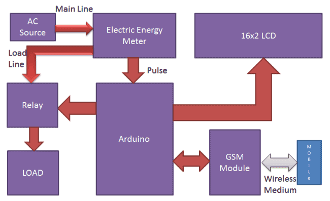
Prepaid Electricity Energy Meter is a good concept in which you can recharge its balance, like we do in our mobile phones. In this project we are building a automated system by using Arduino and GSM module. You can recharge the electricity balance through this system, just by sending a SMS. It can also disconnect the home power supply connection, if there is low or zero balance in the system. And this system will reads the energy meter readings and automatically send some updates to user’s mobile phone like low balance alert, cut off alert, resume alert and recharge alert.
Working explanation:
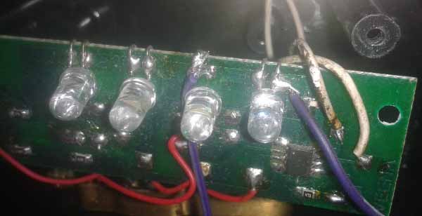
Here we have interfaced electricity energy meter with Arduino using the pulse LED (Calibration or Cal) of electricity Energy meter. We only need to connect tis CAL LED to Arduino through an Optocoupler IC.
Components used:
- Arduino
- GSM Module
- 16x2 LCD
- Analogue Electricity Energy Meter
- Optocoupler 4n35
- Resistors
- POT
- Connecting wires
- Bulb and holder
- SIM card
- Power supply
- Mobile Phone
When we power up the system then it reads previous values of rupees stored in EEPROM and restores them into the variables then checks the available balance with the predefined value and take action according to them, like if available balance is greater than 15 rupees then Arduino turns On the electricity of home or office by using relay. And if balance is less than 15 rupees then Arduino sends a SMS to user phone regarding low balance alert and requesting to recharge soon. And if balance is less than 5 rupees then Arudino turns Off the electricity connection of home and sends a SMS to user’s phone for ‘Light Cut’ alert and requesting to recharge soon. GSM module has been used to send and receive messages, you can check about GSM module and AT commands here.
Now when we need to recharge our system, we can recharge it simply by sending a SMS to the system, through our Cellphone. Like if we want to recharge by 45 bucks then we will send #45*, here # and * are prefix and suffix to the recharge amount. System receives this message and extract recharge amount and update the balance of system. And system again turns On the electricity of the house or office. This flow of working can be understood through the video at the end.
Circuit Description:
Circuit connections for this Wireless Electricity Meter Reading Project, are shown in the diagram; we have used a Arduino UNO for processing all the things used in project. A liquid crystal display is used for displaying the status of Units and remaining balance. Data pins of LCD namely RS, EN, D4, D5, D6, D7 are connected to Arduino digital pin number 7, 6, 5, 4, 3, 2. And Rx and Tx pins of GSM module are directly connected to the Tx and Rx pins of Arduino respectively. And GSM module is powered by using a 12 volt adaptor. A relay is used for switching electricity connection which is connected at pin 12 of Arduino though ULN2003 relay driver.

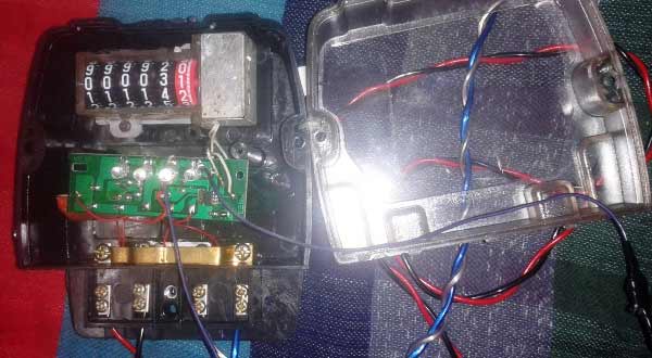
How to Connect Energy Meter with Arduino:
First user need to buy an Analogue Electricity Energy Meter. After it user needs to open it and find the Pulse LED or Cal LED’s terminals (cathode and Anode). Now solder two wires at both the terminals and take it out from the energy meter and then close energy meter and tight the screws.
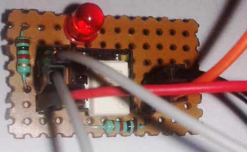
Now user needs to connect anode terminal of LED at pin number 1 of Optocoupler and cathode terminal to pin 2. Pin number four of optocouper should be directly connected to ground. A LED and a Pull-up resistor are connected at pin number 5 of optocoupler. And same terminal should go to the Arduino pin 8 too.
Calculation of Pulses and Units:
Before proceeding for the calculations, first we have to keep in mind the pulse rate of energy meter. There are two pulse rates of energy meter first is 1600 imp/kwh and second is 3200 imp/kwh. So here we are using 3200 imp/kwh pulse rate energy meter.
So first we need to calculate the Pulses for 100watt, means how many times Pulse LED will blink in a minute, for the load of 100 watts.
Pulse= (Pluse_rate*watt*time)/ (1000*3600)
So pulses for 100 watt bulb in 60 seconds, with energy meter of 3200 imp/kwh pulse rate can be calculated as below:
Pulses=3200*100*60/1000*3600
Pulses = ~5.33 pulse per minute
Now we need to calculate Power factor of a single pulse, means how much electricity will be consumed in one pulse:
PF= watt/(hour*Pulse)
PF=100/60*5.33
PF=0.3125 watt in a single pulse
Units= PF*Total pulse/1000
Total pulses in an hour is around 5.33*60=320
Units = 0.3125*320/1000
Units = 0.1 per hour
If a 100 watt bulb is lighting for a day then it will consume
Units =0.1*24
Units = 2.4 Units
And suppose unit rate is at your region is 5 rupees per unit then
You have to pay for 2.4 Units Rs:
Rupees= 2.4*5 = 12 rupees
Programing explanation:
First of all we include required library and Define pins & variables that are required in our project. This can be seen in first few lines of our program code below.
After it we initialize the LCD, serial communication, GSM and display some message message.
After this in loop function we read serial received data if any. And reads pulse from energy meter and show units and balance on LCD.
void setup()
{
  lcd.begin(16,2);
  Serial.begin(9600);
  pinMode(led, OUTPUT);
  .. ...
  ... ....
lcd.print("Circuit Digest");
  lcd.setCursor(0,1);
  delay(2000);
  lcd.print("GSM Initilizing...");
  gsm_init();
  .. ...
  ... ....
After this in loop function we read serial received data if any. And reads pulse from energy meter and show units and balance on LCD.
void loop()
{
  serialEvent();
  rupees=EEPROM.read(1);
  units=rupees/5.0;
  lcd.setCursor(0,0);
  lcd.print("Units:");
  .. ...
  ... ....
void init_sms(),void send_data(String message), and void send_sms() functions have been used to send SMS.
gsm_init() function is used for initializing the GSM module for get ready to operate with the system. In this we first sends AT command to know whether GSM module is connected or not. After it we turned off the echo and then check the network.
void gsm_init()
{
  lcd.clear();
  lcd.print("Finding Module..");
  boolean at_flag=1;
  while(at_flag)
  .. ...
  ... ...
In check_status() function system reads connection and Balance conditions; like whether electricity balance is greater than the defined limit. If balance is less than 15 , then it alerts the user by sending the SMS alert of ‘Low Balance’ and if balance is less than 5 rupees then system will cut the electricity and inform the user by sending SMS using GSM module.
void check_status()
{
  if(rupees>15)
   {
    digitalWrite(relay, HIGH);
    flag1=0;
    .. ...
    ... ....
send_confirmaiton_sms() function is used for sending confirmation message to the user if recharge has been done and it also update the balance in the system.
decode_message() function is used for decoding the amount figure from the SMS message, by using the # and * as starting and ending character.
read_pulse() function is used for reading pulse from the Energy meter through optocoupler IC. And update the unit and balance.
void read_pulse()
{
  if(!digitalRead(pulsein))
   {
    digitalWrite(led, HIGH);
    if(units<1){}
    .. ...
    ... ....
serialEvent() function is used for serial communication and receiving the message.
Complete Project Code
#include<EEPROM.h>
#include <LiquidCrystal.h>
LiquidCrystal lcd(7,6,5,4,3,2);
int led=13;
#define pulsein 8
#define relay 12
unsigned int pusle_count=0;
float units=0;
unsigned int rupees=0;
 float watt_factor=0.3125;
unsigned int temp=0,i=0,x=0,k=0;
char str[70],flag1=0,flag2=0;
String bal="";
void setup()
{
  lcd.begin(16,2);
  Serial.begin(9600);
  pinMode(led, OUTPUT);
  pinMode(pulsein, INPUT);
  pinMode(relay, OUTPUT);
  digitalWrite(pulsein, HIGH);
  lcd.setCursor(0,0);
  lcd.print("Automatic Energy");
  lcd.setCursor(0,1);
  lcd.print("      Meter    ");
  delay(2000);
  lcd.clear();
  lcd.print("Circuit Digest");
  delay(2000);
  lcd.clear();
  lcd.print("GSM Initilizing...");
  gsm_init();
  lcd.clear();
  lcd.print("System Ready");
  Serial.println("AT+CNMI=2,2,0,0,0");
  init_sms();
  send_data("System Ready");
  send_sms();
  delay(1000);
  digitalWrite(led, LOW);
  lcd.clear();
//  EEPROM.write(1,0);
 // rupees=EEPROM.read(1);
}
void loop()
{
    serialEvent();
    rupees=EEPROM.read(1);
    units=rupees/5.0;
    lcd.setCursor(0,0);
    lcd.print("Units:");
    lcd.print(units);
    lcd.print("      ");
    lcd.setCursor(0,1);
    if(rupees<15)
    lcd.print("LOW Balance:");
    else
    lcd.print("Balance:");
    lcd.print(rupees);
    lcd.print("      ");
    read_pulse();
    check_status();
    if(temp==1)
    {
     decode_message();
     send_confirmation_sms();
    }
}
void serialEvent()
{
  while(Serial.available())
  {
    char ch=(char)Serial.read();
    str[i++]=ch;
    if(ch == '*')
    {
      temp=1;
      lcd.clear();
      lcd.print("Message Received");
      delay(500);
      break;
    }
  }
}
void init_sms()
{
   Serial.println("AT+CMGF=1");
   delay(200);
   Serial.println("AT+CMGS=\"+918287114222\"");
   delay(200);
}
void send_data(String message)
{
  Serial.println(message);
  delay(200);
}
void send_sms()
{
  Serial.write(26);
}
void read_pulse()
{
    if(!digitalRead(pulsein))
    {
      digitalWrite(led, HIGH);
      //count++;
      //units=watt_factor*count/1000;
      if(units<1){}
      else
      units--;
      rupees=units*5;
      EEPROM.write(1,rupees);
      while(!digitalRead(pulsein));
      digitalWrite(led,LOW);
     // delay(2000);
    }
}
void check_status()
{
      if(rupees>15)
      {
        digitalWrite(relay, HIGH);
        flag1=0;
        flag2=0;
      }
      if(rupees<15 && flag1==0)
      {
       lcd.setCursor(0,1);
       lcd.print("LOW Balance       ");
       init_sms();
       send_data("Energy Meter Balance Alert:");
       send_data("Low Balance\n");
       Serial.println(rupees);
       delay(200);
       send_data("Please recharge your energy meter soon.\n Thank you");
       send_sms();
       message_sent();
       flag1=1;
      }
      if(rupees<5 && flag2==0)
     {
      digitalWrite(relay, LOW);
      lcd.clear();
      lcd.print("Light Cut Due to");
      lcd.setCursor(0,1);
      lcd.print("Low Balance");
      delay(2000);
      lcd.clear();
      lcd.print("Please Recharge ");
      lcd.setCursor(0,1);
      lcd.print("UR Energy Meter ");
      init_sms();
      send_data("Energy Meter Balance Alert:\nLight cut due to low Balance\nPlease recharge your energy meter soon.\n Thank you");
      send_sms();
      message_sent();
      flag2=1;
    }
}
void decode_message()
{
  x=0,k=0,temp=0;
     while(x<i)
     {
      while(str[x]=='#')
      {
        x++;
        bal="";
        while(str[x]!='*')
        {
          bal+=str[x++];
        }
      }
      x++;
    }
    bal+='\0';
}
void send_confirmation_sms()
{
    int recharge_amount=bal.toInt();
    rupees+=recharge_amount;
    EEPROM.write(1, rupees);
    lcd.clear();
    lcd.print("Energy Meter ");
    lcd.setCursor(0,1);
    lcd.print("Recharged:");
    lcd.print(recharge_amount);
    init_sms();
    send_data("Energy Meter Balance Alert:\nYour energy meter has been recharged Rs:");
    send_data(bal);
    send_data("Total Balance:");
    Serial.println(rupees);
    delay(200);
    send_data("Eelctricity Has Been Connected\nThank you");
    send_sms();
    temp=0;
    i=0;
    x=0;
    k=0;
    delay(1000);
    message_sent();
}

void message_sent()
{
  lcd.clear();
  lcd.print("Message Sent.");
  delay(1000);
}
void gsm_init()
{
  lcd.clear();
  lcd.print("Finding Module..");
  boolean at_flag=1;
  while(at_flag)
  {
    Serial.println("AT");
    while(Serial.available()>0)
    {
      if(Serial.find("OK"))
      at_flag=0;
    }
    delay(1000);
  }
  lcd.clear();
  lcd.print("Module Connected..");
  delay(1000);
  lcd.clear();
  lcd.print("Disabling ECHO");
  boolean echo_flag=1;
  while(echo_flag)
  {
    Serial.println("ATE0");
    while(Serial.available()>0)
    {
      if(Serial.find("OK"))
      echo_flag=0;
    }
    delay(1000);
  }
  lcd.clear();
  lcd.print("Echo OFF");
  delay(1000);
  lcd.clear();
  lcd.print("Finding Network..");
  boolean net_flag=1;
  while(net_flag)
  {
    Serial.println("AT+CPIN?");
    while(Serial.available()>0)
    {
      if(Serial.find("+CPIN: READY"))
      net_flag=0;
    }
    delay(1000);
  }
  lcd.clear();
  lcd.print("Network Found..");
  delay(1000);
  lcd.clear();
}
Comments
nice project
but i want to know
if we are recharging the meter through mobile
from where will be the money deducted ?
This is only demo.
Dear Sir,
I would like to request modification on the code based on my requirement,
Kindly let me know the possibility.
Thanks,
Naeem
hii,
need help ;Currently working on this project ; Programming part is working but I am not able to get the pulse of energy meter;
can u tell in which software u did simulation
How did you get the arduino code to work? can you send me what you have as the original code doesn't compile anymore
same problem .how to count pulse
exactly this is my question too.....
Good Project
I also want to know if we are recharging the meter through mobile
from where will be the money deducted ?
hello,
very nice and innovative project. would you please send me the details so as I can try for my final year project.
read this article carefully and also watch video and then try to understand what we do here?
and for more assistance you may leave me mail
Good evening im currently doing the same project and my objective is to deliver a system that can monitor the energy consumption of end users and automaticaly display the energy consumption and bill information to end users as well. now my problem is i do not want to use GSM Module thus looking for an alternative of how can i do it not through mobile phone.
while uploading the program on board there is a warning comes saying as below
Arduino: 1.8.5 (Windows 8), Board: "Arduino/Genuino Uno"
C:\Users\AMEY_9_96\Documents\Arduino\mm\mm.ino: In function 'void gsm_init()':
C:\Users\AMEY_9_96\Documents\Arduino\mm\mm.ino:218:26: warning: deprecated conversion from string constant to 'char*' [-Wwrite-strings]
if(Serial.find("OK"))
^
C:\Users\AMEY_9_96\Documents\Arduino\mm\mm.ino:234:26: warning: deprecated conversion from string constant to 'char*' [-Wwrite-strings]
if(Serial.find("OK"))
^
C:\Users\AMEY_9_96\Documents\Arduino\mm\mm.ino:250:36: warning: deprecated conversion from string constant to 'char*' [-Wwrite-strings]
if(Serial.find("+CPIN: READY"))
The above 3 warnings come. Is this warning message displaying by arduino ok ??
Dear Sir,
We are also getting the same error.May I know how did you correct the error.
we are working on it but want to know how to recharge the enargy meter
send me the detailed explanation
is the code working bro and can i use it?for final year project
i want ideas on analog elecctronics
DEAR SURE THIS IS WORK PROPARLY? IT'S OUR PROJECT IN FYP KINDLY SOME HELP US MAIL Qudratllah.gujrani73@gmail.com
DEAR SURE THIS IS WORK PROPARLY? IT'S OUR PROJECT IN FYP KINDLY SOME HELP US MAIL Qudratllah.gujrani73@gmail.com
I am doing the same project but i don't have the clear idea about the pulse(RED LED) connections with the optocopler. I gave the same connections as mentioned above in your project but still getting wrong output.
1.could you mention again the connections of pulse out to all 6 pins of opto ??
2. After consuming how much power the reading in the red box in the meter will change by 1 unit ?
may be you are connecting with the wrong LED.
Project concept is very good and it's working but unite or amount is reduced with every pulse.It should reduce one unit or amount for 3200 pulse not one pulse so please help in doing so
help
Can i use a keypad to recharge instead of gsm?if yes can you please tell me how to interface and also the code
Yes you can use keypad to recharge it, you need to change the code and connections accordingly. Check this link for Interfacing Keypad with Arduino.
sir,
i doing the same project, so can you please send more circuit details and programme code
this is very smart project. and how can i find the cal led that u use insted of energy meter in proteus
sir, where did you get units 7.6 and bal. 38 ?are these included in the program?
It has been previously recharged and value has been saved in EEPROM. EEPROM can keep value when Arduino is OFF. When Arduino is turned ON the saved value has been read from EEPROM.
good project, i do the this project how can we get the energy meter in protues liberary
Do you have info on how we can manually input the number of inputs into the System instead of getting it from energy meter...and also Do you have a proteus Simulation of this project
truly appreciate the work. it would be of great help if you could tell how to import sim900 gsm module and energy meter module in proteus
which simulator you used to design the circuit .
wich library you used for energy meter in proteus
We only draw the energy meter and gsm module.
there is no library for that component..
Arduino IDE LiquidCrystal library file additionally created or it inbuilt in IDE.......
I connect all these circuit diagram and then uploading the Arduino it's not uploaded , so sir you are heartly requested to send me document of project
how to get gsm module ,16 pin lcd and energy meter
Can I use digital meter in place of analogue meter...
Yes you can, basically you need to sense the Pulse rate of energy meter using Arduino. So you can do that with Digital meter, jut find out the way to find it pulse like in this project Cal LED is used to calculate its pulses.
Thanks sir your project is innovative and match exactly the kind I'm designing only with few modifications.
I'm using Hall effect sensor instead of analog meter and I found it difficult incorporating gsm modem as a mean of trasmission and control. With modem the gsm credit purchase can be converted when recharge to killowat unit meaning the meter can be recharge through any internet / gsm medium and the power industry will access and control the meter through gsm. Kindly help as this project is an investment opportunity in life
our thesis is the same as your sir
but we are just using a coin slot for load of the Energy
can you please give us some advice Thanks in Advance Sir :)
Someone please explain me the working of electricity meter in this project.
Basically we need to calculate the no of times Pulse LED blinks for the particular Load, based on that we can calculate the Units consumed. We have clearly explained this in our Article.
Thanks sir, this project idea is really very good and also applicable but my question is that: How will the UTILITIES get their benefit if installed at home or any other commercial use?
can i use rfid to recharge my energy meter .
nice and cool project, thanks alot.....
what the function optocoupler in this project?
This is a very good reference for my final year project, but if i may ask, what library did you use to include the energy meter, and is it possible yo omit the ULN2003 driver? oh and if you may, would you mind sharing your proteus drawing with me? email me at [] . thanks in advance
Also i would like to ask, if a 9900 gsm is compatible in replacing sim900?
doing the same project ....how did u add the energy meter on proteus
may i ask, when i compiled your code, i get exit status 1, what went wrong?
I need help regarding this project... Cz some problems occurs during recharging
if we are recharging the meter through mobile
from where will be the money deducted ?
It is just the Demo project, in actual scenario either money will be deducted from your mobile balance or you need to have some digital wallet with your Electricity Board from where the money will be deducted.
This is a full coding for this project??
Very much innovative idea.I Like to make it my final year project. Help me for that.
finally completed this project .........thank it is verrrrrry helpfullllllllll
Hey i am not getting the confirmation msg so plzz help me with details...my circuit us working ..i think there is some problem in program so can u help me
How much this cost you... Prepaid energy meter and what are main components
Kindly give send me code and connections
Is this code worked correctly?
can you please email me the working code and provide paid assistance with the project?
Sir,can you give details of simulation on proteus and component ratings which are used in project
thank you a lot sir
i'm doing the same for my final year project so can you please send me more details.
its a great project indeed i would like to have more details may you please contact me or put your so that i may contact you
sir i understood whole things but i do not know how to make energy meter in proteus....because there is no library function for energy meter..........
Sir plz help after uplodind coding and connect all parameter
It shows module finding..
Not going ahed
Sir? Can you please explain how opto coupler works in more deep explanation pls
Optocoupler basically isolates two circuits by the mean of Light. It consist a IR led and a photo diode, everytime IR led emits light the photo diode conducts. Here in this project Optocoupler conducts with each electric pulse by the Energy meter. There are lot of tutorials on internet about it.
sir can you please recharge concept and how connect the call led in digital meter...can i use ir sensor in this project or not....
What are the relay specifications? Which volt relay is to be used?
sir can i used SIM800 instead of SIM900A?
There is some problem in the code. I am continuously receiving the "System Ready" message. Please help
i just want to know how u people draw the ckt diagram just tell me which software plzz help me
sir some problems occured and not receive the alert message so please help
sir some problems occured and not receive the alert message so please help
code is having some problem. the conversion of pulses into units are not proper kindly give a reply
.
Hi.. I m doing the same project. Bt I m using an IR sensor instead of optocoupler. Can u please help me how to connect the energy meter to IR sensor to get the pulses
Sir
When I send the message from my mobile for recharge then Energy meter it's not working .I think some problem is present in programming.Please give me solution of the programming.I want your help if you give your contact number it's helpful for me.
Sir can you please send me the correct components and it's value required to design this project
While sending Recharge message it won't take the recharged amount and also it won't display
sir, can you send me the details code for the project because the code presented here may be not correct for proper function.
thanks in advance.
Dear Concern,
Very Effective project. It will be very helpfull for me if you provide the relay voltage.
Thanking You
Dear Concern,
Ignore my previous mail. I got the my Relay Voltage reply it is 5V.
Thanks
sir.... please tell me whether the code is correct and in working mode or not please sir ????

thanks so good projects