

The name of the circuit itself infers the application. This circuit triggers the alarm if the door of Fridge is left open for the long time. When the door of the refrigerator is left open, the temperature inside the cabin will increase. This rise in temperature will be sensed by thermostat and try to cool down the cabin. It will always try to maintain constant temperature of the system. The compressor will be working continuously to remove the heat from cabin, this increases the power consumption from the receptacle. Also, continuous usage under this condition would reduce the life of compressor and probably do malfunction.
Hence, this Fridge Door Alarm Circuit is a good solution which will indicate the user about the door in prolonged open condition. We can also set different pre-set time after which the audible indication has to be given. This is done here by using the versatile 555 timer IC under astable multivibrator mode and LDR. As soon as we open the Door of refrigerator, LDR senses it and start the countdown using 555 Timer, and after a preset time the buzzers starts beeping as alarm signal.
Components Required:
- 555 timer IC – 2Nos
- 5mm LDR – 1No.
- Buzzer – 1No.
- Diode (1N4007 or 1N4001) – 1No.
- Capacitor, 47uF(Electrolytic) – 1No.
- Capacitor, 0.1uF(Ceramic) – 1No.
- Resistors (10kὨ - 1; 470kὨ -1; 150kὨ -2; 100Ὠ -1)
- Breadboard
- Connecting wires
Fridge Door Alarm Circuit Diagram and Explanation:

The two 555 timers are connected in Astable multivibrator mode. The key components in the circuit are LDR (Light Dependent Resistor) and 555 Timer IC.
LDR (Light Dependent Resistor):
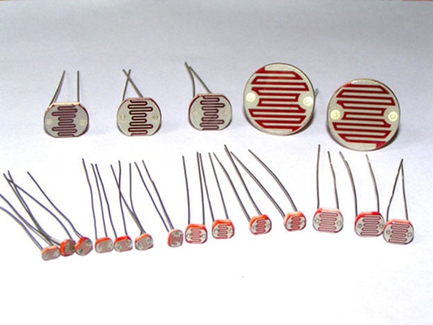
LDR works under the principle of Photo Conductivity. The conductance of the material inside the element increases when light falls over it. In terms of resistance, the value of resistance decreases when light falls over it and resistance will be large in dark surrounding. The resistance is directly proportional the light over the material, check the table below:
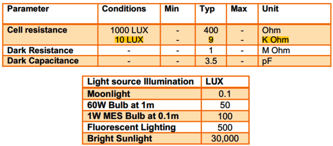
There are several types of LDR like 3mm LDR, 4mm LDR, 5mm LDR, 7mm LDR and etc. The part used here is 5mm LDR. Using the above data we have considered the resistance divider as 10k with 5mm LDR.
555 Timer in Astable operation:
Astable multivibrator has no stable states. The output swings between high and low based on the timing resistor and capacitor.
The formulae to calculate the time delay is as below,
Time (Sec) = 1.1 x (R2 + R3) x C1
You can also use this 555 timer calculator to calculate the output values.
Here in this Fridge Door Open Alarm Circuit, we have used two 555 ICs, one for calculate the ‘Fridge door Open time duration’ after which the Buzzer should be triggered, and second 555 IC is for controlling the Buzzer beeping pattern.
Below we have calculated Time delay for Buzzer to be triggered and selected the resistor values accordingly. Here the Time delay means the duration for which the Refrigerator Door is left open. This is done by first 555 IC in the circuit.
Time (Sec)=1.1 × (620kὨ ± 5%) × 47uF
Time =30.4 secs
Hence, R2=150kὨ, R3=470kὨ in series and C1=47uF
Below we have calculated the Time Delay for second 555 IC, which is controlling Buzzer Beeping Time Period. In this case time delay is calculated as,
Time (Sec) =1.1 × (470kὨ ± 5%) × 0.1uF
Time = 0.5 secs
Hence, R5=470kὨ and C2=0.1uF (The buzzer turns ON and OFF at this time frame)
Learn more about 555 Timer Astable multivibrator mode here.

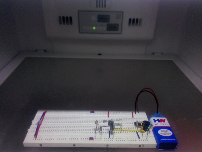
Working of Refrigerator Door Open Alarm Circuit:

The whole circuit is powered by a 9V battery. When the fridge door is closed, it is dark and the resistance of the LDR is nearly 1MὨ as given in datasheet. The output voltage of the potential divider appears across the capacitor and it remains in charged condition (Voltage higher than 2/3Vcc) making the output LOW. When we open the Fridge, the light falls over LDR which lowers down the resistance of LDR and causing the capacitor to discharge which in this RC combination it is 30 secs. After this (Voltage lower than 2/3Vcc), the output starts to oscillate at certain frequency and output is HIGH. Again, the capacitor charges and reaches a threshold continued by discharge of the capacitor. This continues till the LDR resistance goes high which will happen in the absence of light (door is closed).
This makes the second 555 timer to oscillate and the output becomes HIGH and LOW causing the buzzer connected to output to beep in a pattern which is combinational cause of the first timer oscillations and the second timer internal oscillation. During HIGH condition of first timer output, the second timer master reset will happen. Thus, the capacitor C2 charges (Voltage higher than 2/3Vcc) and output goes LOW. In a short span the capacitor starts to discharge (Voltage lower than 2/3Vcc) causes the output HIGH. Hence, the buzzer connected to output becomes pulsed beep sound.
Below is the Demonstration Video for this Fridge Door Alarm Circuit.
Comments
how many volts capacitor did
how many volts capacitor did you use? thanks
The whole system is powered
The whole system is powered with only a 9V battery so you can use any voltage capacitor thats above 9V
about time delay
why there is 1.1 in the time delay calculation formula. Why not 0.69
You might have to check the
You might have to check the datasheet of 555 timer to answer this question. how did you arrive at the number 0.69?
is it ok to leave the battery
is it ok to leave the battery and components inside the freezer? would it not be damaged or maybe spoil/contaminate the foods?
For temporary application it
For temporary application it is okay to leave the battery inside the fridge. But if you are planing on long time use! then use a proper casing
What type of buzzer are you
What type of buzzer are you using? I tried to hook up a active buzzer but its not working then I tried to hook up an led and it seems to work.
I was able to make it work
I was able to make it work using an active buzzer, though it seems to consume a lot of power, my fresh 9 volt battery did'nt last a few days. Can you plese give me some tips to extend the battery life for this circuit? thanks!
Buy a decent 9V battery
Most of the 9V battery that we find in market are cheap and hence they wont last long. Find a good one and it should last for a day or two minimum
What is the purpose and
What is the purpose and function of the diode after the potential divider?
To prevent reverse voltage
To prevent reverse voltage from the 555 timer pin
reed switch instead of ldr?
I made this circuit and it is working very good for 1 year ago, but now I want to change de LDR for reed switch because my refrigerator has internal light but my freezer do not have and i only can use this in the refrigerator, with reed switches I will can use in both. it is possible and easy to adapt this circuit to use reed switches instead of LDR?

Bravo, thanks!