

Measuring the voltage and current will always be helpful while making or debugging any electrical system. In this project we are going to make our own Digital Ammeter using PIC16F877A Microcontroller and current sensor ACS712-5A. This project can measure both AC and DC current with a range of 0-30A with an accuracy of 0.3A. With few modifications on the code you can also use this circuit to measure up to 30A. So let us get started!!!
Materials Required:
- PIC16F877A
- 7805 Voltage Regulator
- ACS712 current Sensor
- 16*2 LCD display
- A junction box and load (Just for testing)
- Connecting wires
- Capacitors
- Breadboard.
- Power supply – 12V
Working of ACS712 Current Sensor:
Before we start building the project it is very important for us to understand the working of the ACS712 Current sensor as it is the key component of the project. Measuring current especially AC current is always a tough task due to the noise coupled with it improper isolation problem etc. But, with the help of this ACS712 module which was engineered by Allegro thing have become a lot easier.
This module works on the principle of Hall-effect, which was discovered by Dr. Edwin Hall. According his principle, when a current carrying conductor is placed into a magnetic field, a voltage is generated across its edges perpendicular to the directions of both the current and the magnetic field. Let us not get too deep into the concept but, simply put we use a hall sensor to measure the magnetic field around a current carrying conductor. This measurement will be in terms of millivolts which we called as the hall-voltage. This measured hall-voltage is proportional to the current that was flowing through the conductor.
The major advantage of using ACS712 Current Sensor is that is can measure both AC and DC current and it also provides isolation between the Load (AC/DC load) and Measuring Unit (Microcontroller part). As shown in the picture we have three pins on the module which are Vcc, Vout and Ground respectively.

The 2-pin terminal block is where the current carrying wire should be passed through. The module work on +5V so the Vcc should be powered by 5V and the ground should be connected to Ground of the system. The Vout pin has an offset voltage of 2500mV, meaning when there is no current flowing through the wire then the output voltage will be 2500mV and when current flowing is positive, the voltage will be greater than 2500mV and when the current flowing is negative, the voltage will be less than 2500mV.
We will be using the ADC module of the PIC microcontroller to read the output voltage (Vout) of the module, which will be 512(2500mV) when there is no current flowing through the wire. This value will reduce as the current flows in negative direction and will increase as the current flows in positive direction. The below table will help you understand how the output voltage and ADC value varies based on the current flowing through the wire.
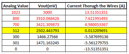
These values were calculated based on the information given in the Datasheet of ACS712. You can also calculate them using the below formulae:
Vout Voltage(mV) = (ADC Value/  1023)*5000
Current Through the Wire (A) = (Vout(mv)-2500)/185
Now, that we know how the ACS712 Sensor works and what we could expect from it. Let us proceed to the circuit diagram.
Circuit Diagram:
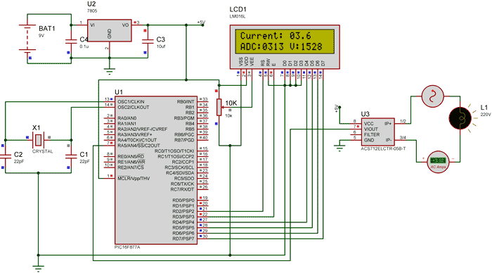
The complete circuit diagram of this Digital Ammeter Project is shown in the image below.

The complete digital current meter circuit works on +5V which is regulated by a 7805 Voltage regulator. We have used a 16X2 LCD to display the value of the current. The output pin of the current Sensor (Vout) is connected to the 7th pin of the PIC which is the AN4 to read the Analog voltage.
Further the pin connection for the PIC is shown in the table below
|
S.No: |
Pin Number |
Pin Name |
Connected to |
|
1 |
21 |
RD2 |
RS of LCD |
|
2 |
22 |
RD3 |
E of LCD |
|
3 |
27 |
RD4 |
D4 of LCD |
|
4 |
28 |
RD5 |
D5 of LCD |
|
5 |
29 |
RD6 |
D6 of LCD |
|
6 |
30 |
RD7 |
D7 of LCD |
|
7 |
7 |
AN4 |
Vout of Current Sesnor |
You can build this digital ammeter circuit on a breadboard or use a perf board. If you have been following the PIC tutorials then you can also reuse the hardware that we used for learning PIC microcontrollers. Here we have used the same perf Board which we have built for LED Blinking with PIC Microcontroller, as shown below:
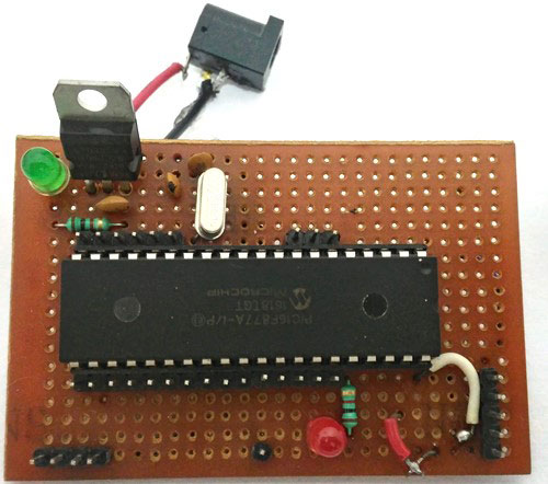
Note: It is not mandatory for you to build this board you can simply follow the circuit diagram and build you circuit on a bread board and use any dumper kit to dump your program into the PIC Microcontroller.
Simulation:
This current meter circuit can also be simulated using Proteus before you actually proceed with your Hardware. Assign the hex file of the code given at the end of this tutorial and click on play button. You should be able to notice the current on the LCD display. I have used a Lamp as an AC load, you can vary the internal resistance of the Lamp by clicking on it to vary the current flowing through it.
As you can see in the above picture, the Ammeter shows the actual current flowing through the Lamp which is around 3.52 A and the LCD shows the current to be around 3.6A. However in practical case we might get Error up to 0.2A. The ADC value and voltage in (mV) is also shown on the LCD for your understanding.
Programming the PIC Microcontroller:
As told earlier, the complete code can be found at the end of this article. The code is self explained with comment lines and just involves the concept of interfacing a LCD with PIC Microcontroller and Using ADC module in PIC Microcontroller which we have already covered in our previous tutorials of learning PIC Microcontrollers.
The value read from the sensor will not be accurate since the current is alternating and is also subjected to noise. Hence we read the ADC value for 20 Times and average it to get the appropriate current Value as shown in the code below.
We have used the same formulae which was explained above to calculate the voltage and Current value.
        for (int i=0; i<20;i++) //Read value for 20 Times
        {
        adc=0;
        adc=ADC_Read(4); //Read ADC
        Voltage = adc*4.8828; //Calculate the Voltage

        if (Voltage>=2500) //If the current is positive
              Amps += ((Voltage-2500)/18.5);

        else if (Voltage<=2500) //If the current is negative
              Amps += ((2500-Voltage)/18.5);
        }

        Amps/=20;  //Average the value that was read for 20 times
Since this project can also read AC current the current flow will be negative and positive as well. That is the value of the output voltage will be above and below 2500mV. Hence as shown below we change the formulae for negative and positive current so that we do not get negative value.
        if (Voltage>=2500) //If the current is positive
              Amps += ((Voltage-2500)/18.5);

        else if (Voltage<=2500) //If the current is negative
              Amps += ((2500-Voltage)/18.5);
Using a 30A current sensor:
If you need to measure current more than 5A you can simply buy a ACS712-30A module and interface it the same way and change the below line of code by replacing 18.5 with 0.66 as shown below:
        if (Voltage>=2500) //If the current is positive
              Amps += ((Voltage-2500)/0.66);

        else if (Voltage<=2500) //If the current is negative
              Amps += ((2500-Voltage)/0.66);
Also check 100mA Ammeter using AVR Microcontroller if you want to measure low current.

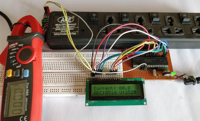
Working:
Once you have programmed the PIC Microcontroller and made your hardware ready. Simply power on the load and your PIC microcontroller you should be able to see the current passing through the wire displayed in your LCD screen.
NOTE: IF you are using a ASC7125A module make sure your load does not consume more than 5A also use higher gauge wires for current carrying conductors.
The complete working of the PIC microcontroller based ammeter project is shown in the Video below. Hope you got the project working and enjoyed doing it. If you have any doubts you can write them on the comment section below or post them on our forums.
Complete Project Code
/*
Digital Ammeter for PIC16F877A
 * Code by: B.Aswinth Raj
 * Dated: 27-07-2017
 * More details at: www.CircuitDigest.com
 */

#define _XTAL_FREQ 20000000
#define RS RD2
#define EN RD3
#define D4 RD4
#define D5 RD5
#define D6 RD6
#define D7 RD7

#include <xc.h>

#pragma config FOSC = HS        // Oscillator Selection bits (HS oscillator)
#pragma config WDTE = OFF       // Watchdog Timer Enable bit (WDT disabled)
#pragma config PWRTE = ON       // Power-up Timer Enable bit (PWRT enabled)
#pragma config BOREN = ON       // Brown-out Reset Enable bit (BOR enabled)
#pragma config LVP = OFF        // Low-Voltage (Single-Supply) In-Circuit Serial Programming Enable bit (RB3 is digital I/O, HV on MCLR must be used for programming)
#pragma config CPD = OFF        // Data EEPROM Memory Code Protection bit (Data EEPROM code protection off)
#pragma config WRT = OFF        // Flash Program Memory Write Enable bits (Write protection off; all program memory may be written to by EECON control)
#pragma config CP = OFF         // Flash Program Memory Code Protection bit (Code protection off)


//LCD Functions Developed by Circuit Digest.
void Lcd_SetBit(char data_bit) //Based on the Hex value Set the Bits of the Data Lines
{
if(data_bit& 1)
D4 = 1;
else
D4 = 0;

if(data_bit& 2)
D5 = 1;
else
D5 = 0;

if(data_bit& 4)
D6 = 1;
else
D6 = 0;

if(data_bit& 8)
D7 = 1;
else
D7 = 0;
}

void Lcd_Cmd(char a)
{
RS = 0;
Lcd_SetBit(a); //Incoming Hex value
EN  = 1;
        __delay_ms(4);
        EN  = 0;
}

void Lcd_Clear()
{
Lcd_Cmd(0); //Clear the LCD
Lcd_Cmd(1); //Move the curser to first position
}

void Lcd_Set_Cursor(char a, char b)
{
char temp,z,y;
if(a== 1)
{
 temp = 0x80 + b - 1; //80H is used to move the curser
z = temp>>4; //Lower 8-bits
y = temp & 0x0F; //Upper 8-bits
Lcd_Cmd(z); //Set Row
Lcd_Cmd(y); //Set Column
}
else if(a== 2)
{
temp = 0xC0 + b - 1;
z = temp>>4; //Lower 8-bits
y = temp & 0x0F; //Upper 8-bits
Lcd_Cmd(z); //Set Row
Lcd_Cmd(y); //Set Column
}
}

void Lcd_Start()
{
  Lcd_SetBit(0x00);
  for(int i=1065244; i<=0; i--)  NOP();
  Lcd_Cmd(0x03);
__delay_ms(5);
  Lcd_Cmd(0x03);
__delay_ms(11);
  Lcd_Cmd(0x03);
  Lcd_Cmd(0x02); //02H is used for Return home -> Clears the RAM and initializes the LCD
  Lcd_Cmd(0x02); //02H is used for Return home -> Clears the RAM and initializes the LCD
  Lcd_Cmd(0x08); //Select Row 1
  Lcd_Cmd(0x00); //Clear Row 1 Display
  Lcd_Cmd(0x0C); //Select Row 2
  Lcd_Cmd(0x00); //Clear Row 2 Display
  Lcd_Cmd(0x06);
}

void Lcd_Print_Char(char data)  //Send 8-bits through 4-bit mode
{
   char Lower_Nibble,Upper_Nibble;
   Lower_Nibble = data&0x0F;
   Upper_Nibble = data&0xF0;
   RS = 1;             // => RS = 1
   Lcd_SetBit(Upper_Nibble>>4);             //Send upper half by shifting by 4
   EN = 1;
   for(int i=2130483; i<=0; i--)  NOP();
   EN = 0;
   Lcd_SetBit(Lower_Nibble); //Send Lower half
   EN = 1;
   for(int i=2130483; i<=0; i--)  NOP();
   EN = 0;
}

void Lcd_Print_String(char *a)
{
int i;
for(i=0;a[i]!='\0';i++)
  Lcd_Print_Char(a[i]);  //Split the string using pointers and call the Char function
}
/*****End of LCD Functions*****/


//**ADC FUnctions***//
void ADC_Initialize()
{
  ADCON0 = 0b01000001; //ADC ON and Fosc/16 is selected
  ADCON1 = 0b11000000; // Internal reference voltage is selected
}

unsigned int ADC_Read(unsigned char channel)
{
  ADCON0 &= 0x11000101; //Clearing the Channel Selection Bits
  ADCON0 |= channel<<3; //Setting the required Bits
  __delay_ms(2); //Acquisition time to charge hold capacitor
  GO_nDONE = 1; //Initializes A/D Conversion
  while(GO_nDONE); //Wait for A/D Conversion to complete
  return ((ADRESH<<8)+ADRESL); //Returns Result
}
//***End of ADC Functions***//

int main()
{
    int adc=0; //Variable to read ADC value
    int a1,a2,a3,a4; //Variable to split ADC value into char

    int Voltage; //Variable to store voltage
    int vl1,vl2,vl3,vl4; //Variable to split Voltage value into char

    int Amps; //Variable to store Amps value
    int Am1,Am2,Am3,Am4; //Variable to split Amps value into char

    TRISD = 0x00; //PORTD declared as output for interfacing LCD
    TRISA4 =1; //AN4 declared as input
    ADC_Initialize();
    Lcd_Start();
    Lcd_Clear();

    while(1)
    {
        /***Current Calculation*****/
        for (int i=0; i<20;i++) //Read value for 20 Times
        {
        adc=0;
        adc=ADC_Read(4); //Read ADC
        Voltage = adc*4.8828; //Calculate the Voltage

        if (Voltage>=2500) //If the current is positive
              Amps += ((Voltage-2500)/18.5);

        else if (Voltage<=2500) //If the current is negative
              Amps += ((2500-Voltage)/18.5);
        }
        Amps/=20;  //Average the value that was read for 20 times
        /******Current Calculation******/


        //**Display current**//
        Am1 = (Amps/100)%10;
        Am2 = (Amps/10)%10;
        Am3 = (Amps/1)%10;
        Lcd_Set_Cursor(1,1);
        Lcd_Print_String("Current: ");
        Lcd_Print_Char(Am1+'0');
        Lcd_Print_Char(Am2+'0');
        Lcd_Print_Char('.');
        Lcd_Print_Char(Am3+'0');

         //**Display ADC**//
        a1 = (adc/1000)%10;
        a2 = (adc/100)%10;
        a3 = (adc/10)%10;
        a4 = (adc/1)%10;
        Lcd_Set_Cursor(2,1);
        Lcd_Print_String("ADC:");
        Lcd_Print_Char(a1+'0');
        Lcd_Print_Char(a2+'0');
        Lcd_Print_Char(a3+'0');
        Lcd_Print_Char(a4+'0');

      //**Display Voltage**//
        vl1 = (Voltage/1000)%10;
        vl2 = (Voltage/100)%10;
        vl3 = (Voltage/10)%10;
        vl4 = (Voltage/1)%10;
        Lcd_Print_String(" V:");
        Lcd_Print_Char(vl1+'0');
        Lcd_Print_Char(vl2+'0');
        Lcd_Print_Char(vl3+'0');
        Lcd_Print_Char(vl4+'0');

    }
    return 0;
}
Comments
Display is not visible
Dear Sir,
I had designed this project in the common PCB board and the given given program is successfully debug inside the PIC16f877a but the display is blank . I had checked all the connection but i cant find any fault . kindly please help me to solve this problem
Check you LCD connections.
Check you LCD connections. There should be some pblm with it. Try a simple LCD program to make sure your LCD is working
based on program
I had design a project based on the digital ammeter.But I cannot create hex file for my project.we are trying to create the hex file in mp lab xide.but it does not compile .please give your mplab lab file for me.the above c code is copmpilig some error that #include <xc.h> and some another mitakes,.so please help me.
CORRECTION IN FORMULA
Sir, in working you have explained calculation as Current Through the Wire (A) = (Vout(mv)-2500)/185 where all 2500, Vout and 185 are in mv hence we get current in A... and in code, you've written
Amps += ((2500-Voltage)/18.5);
WHY 18.5 instead of 185???
Sorry its a typo. Even in the
Sorry its a typo. Even in the explanation it should have been 18.5
Is it a typing mistake in
Is it a typing mistake in data sheet?? I checked with data sheet, it says sensitivity=185mV/I.
Hence, for 1A current, voltage will be 185mV and so for 'I' current, 'I*185mV'
considering voltage for 0A current i.e 2500mV,
Vtotal mV=185*I mV + 2500mV
185*I= VtotalmV-2500mV
I= (Vtotal-2500) mV / 185 mV
so we get current in A.
I just need to know that is this calculation (as also in your explanation) is wrong? if yes, what mistake am i doing? and if not, why 18.5 is taken in code instead of 185???
Sir, i have the same doubt...
Sir, i have the same doubt... sensitivity given in datasheet is 185mv/A... so for 1A current the voltage will be 185mv and for IA current, voltage is 185*I...
Vtotalmv=185*Imv + 2500mv
So, 185*Imv=(Vtotal-2500)mv
So, I=(Vtotal-2500)/185 (as given in your explanation too)...
Am i doing something wrong in calculation? And if i am not, why there is 18.5 in formula given in code instead of 185?? Please answer, i have to answer my teacher for the same question!
Okay here is the answer for
Okay here is the answer for all your questions
The correct formulae is
Amps =(Vtotal-2500)/185
But on the variable Amps used in this project is of Integer type and we also have to get the digit value after the decimal point. For example if the value of analog voltage is 1024 and the value of Vtotal is 5000 then
Amps =(Vtotal-2500)/185
Amps =((5000-2500)/185)
Amps = 13.5
In this case if we use 185 the value that will be stored in Amps will only be 13, since it is of integer type. Hence we cannot show the value after point.
But, if we use 18.5 instead of 185
Amps =((5000-2500)/18.5)
Amps = 135
The value 135 will be stored in the integer variable Amps. While displaying this value we split into digits and put a decimal point before last digit so that it looks like 18.5 while displayed as explained in given lines of code. This is a very common method employed by programmer to avoid the usage of float variable.
Software Queries
Hope you would be having a good day. Can you please tell me which software can I use to make this code's hex file?
Sir, can you please provide…
Sir, can you please provide the proteus and the compiled hex file?

Very important project