
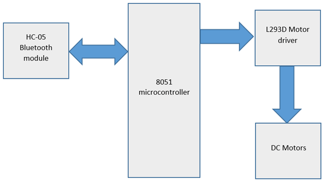
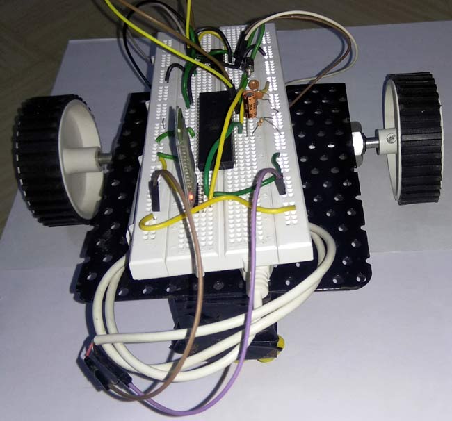
In this project we are going to build an Android Phone controlled robot using 8051 microcontrollers and Bluetooth module. The robot is designed using DC motors and the direction of DC motors will be controlled by the commands received from the android application. The status of the robot is sent back to the Android app. This project will also help for interfacing of HC-05 Bluetooth module with 8051 microcontrollers. We already used Bluetooth module to control home appliances with 8051.
Components Required:
- 8051 microcontroller (AT89S52)
- HC-05 Bluetooth module
- L293D Motor Driver
- Robot chassis
- DC Motors (2)
- Wheels (2)
- Castor Wheel
- Jumper wires
- Bluetooth terminal android app
Circuit Diagram:

8051 Microcontroller:
8051 microcontroller is a 8-bit microcontroller which has 128 bytes of on chip RAM, 4K bytes of on chip ROM, two timers, one serial port and four 8bit ports. 8052 microcontroller is an extension of 8051 microcontroller. In this project we are using AT89S52 microcontroller. The table below shows the comparison of 8051 family members.
|
Feature |
8051 |
8052 |
|
ROM (in bytes) |
4K |
8K |
|
RAM (bytes) |
128 |
256 |
|
Timers |
2 |
3 |
|
I/O pins |
32 |
32 |
|
Serial port |
1 |
1 |
|
Interrupt sources |
6 |
8 |

HC-05 Bluetooth Module:
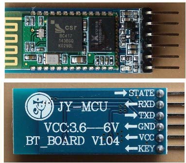
HC-05 is a serial Bluetooth module. It can be configured using AT commands. It can work in three different configurations (Master, Slave, Loop back). In our project we will be using it as a slave. The features of HC-05 module includes,
- Typical -80dBm sensitivity.
- Default baud rate: 9600bps , 8 data bits , 1 stop bit , no parity.
- Auto-pairing pin code: “1234” default pin code
- It has 6 pins.
- Vcc and Gnd pins are used for powering the HC-05.
- Tx and Rx pins are used for communicating with the microcontroller.
- Enable pin for activating the HC-05 module. when it is low , the module is disabled
- State pin acts status indicator. When it is not paired/connected with any other Bluetooth device, LED flashes continuously. When it is connected/paired with any other Bluetooth device, then the LED flashes with the constant delay of 2 seconds.
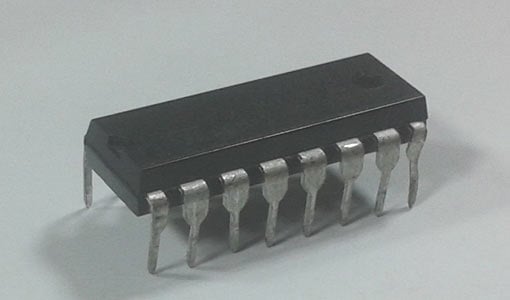
L293D Motor Driver IC:
L293D is a dual H-bridge motor driver IC. This acts as a current amplifier, the output of L293D drives the DC Motors. It contains two inbuilt H-bridge circuits. In common mode of operation , it can drive two dc motors simultaneously in both the directions. The below table shows the pin description of L293D IC. Here are some projects using L293D Motor Driver.
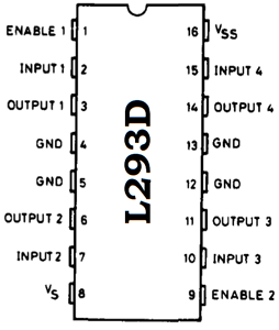
Pin Description
|
Pin No. |
Name |
Function |
|
1 |
Enable 1,2 |
Enable pin for motor 1 |
|
2 |
Input 1 |
Input 1 for motor 1 |
|
3 |
Output 1 |
Output 1 for motor 1 |
|
4 |
Gnd |
Ground (0V) |
|
5 |
Gnd |
Ground (0V) |
|
6 |
Output 2 |
Output 2 for motor 1 |
|
7 |
Input 2 |
Input 2 for motor 1 |
|
8 |
Vcc 2 |
Supply voltage for motors(5V) |
|
9 |
Enable 3,4 |
Enable pin for motor 1 |
|
10 |
Input 3 |
Input 1 for motor 2 |
|
11 |
Output 4 |
Output 1 for motor 2 |
|
12 |
Gnd |
Ground (0V) |
|
13 |
Gnd |
Ground (0V) |
|
14 |
Output 4 |
Output 2 for motor 2 |
|
15 |
Input 4 |
Input 2 for motor 2 |
|
16 |
Vcc 1 |
Supply voltage (5V) |
Working of Android Phone Controlled Robot:
In this Smart Phone controlled Robot, the user of android app sends the data to 8051 microcontroller through HC-05 module. The received data is compared in 8051 microcontroller and the decision is made accordingly. The below table shows the direction of motors and status of robot for different received characters.
|
Received character |
Motor 1 |
Motor 2 |
Status of robot |
|
f |
Forward |
Forward |
Moves forward |
|
b |
Backward |
Backward |
Moves backward |
|
r |
Forward |
Backward |
Moves Right |
|
l |
Backward |
Forward |
Moves left |
|
s |
Off |
Off |
Stopped |
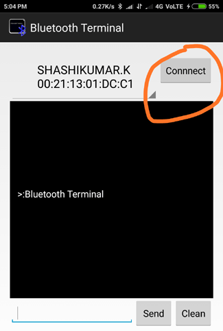
The Bluetooth terminal app allows us to emulate a Bluetooth terminal. This app supports bidirectional communication and this app is compatible with most of the devices.
The steps below show how to install and use this app.
1. Download and install Bluetooth terminal app on your android phone. The app can be downloaded from the below link.
https://play.google.com/store/apps/details?id=ptah.apps.bluetoothterminal
2. After installing the app, open the app and turn on Bluetooth.
3. Select the device and click on connect option. After successful connection, we can start sending data to HC-05 module.
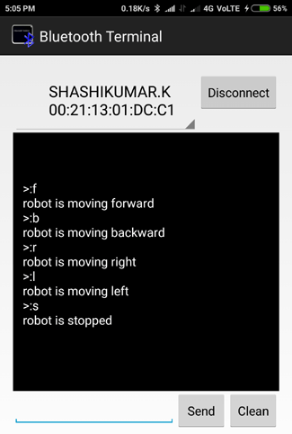
Check the Code Explanation below to see how the character is sent and received by 8051 Microcontroller to rotate the required motors.
Code explanation:
The complete C program and demonstration Video for this project is given at the end of this project. The code is split into small meaningful chunks and explained below.
For L293D interfacing with 8051 microcontrollers, we have to define pins on which L293D is connected to 8051 microcontroller. In1 pin of motor 1 is connected to P2.0, In2 pin of motor 1 is connected to P2.1, In1 pin of motor 2 is connected to P2.2, In2 pin of motor 2 is connected to P2.3
sbit m1f=P2^0;             // in1 pin of motor1
sbit m1b=P2^1;             // in2 pin of motor1
sbit m2f=P2^2;             // in1 pin of motor2
sbit m2b=P2^3;             // in2 pin of motor2
Next we have to define some functions which are used in the program. Delay function is used to create specified time delay. Txdata function is used to transmit data through serial port . Rxdata function is used to receive data from serial port.
void delay(unsigned int)  ;             //function for creating delay
char rxdata(void);                           //function for receiving a character through serial port of 8051
void txdata(unsigned char);        //function for sending a character through serial port of 8051
In this part of the code we are going to configure 8051 microcontroller for serial communication. TMOD register is loaded with 0x20 for timer 1, mode 2 (auto reload). SCON register is loaded with 0x50 for 8 data bits, 1 stop bit and receive enabled. TH1 register is loaded with 0xfd for baud rate of 9600 bits per second. TR1=1 is used to start the timer.
  TMOD=0x20;
   SCON=0x50;
   TH1=0xfd;
   TR1=1;
In this part of the code, the returned character of rxdata function is stored in the variable ‘s’ for further use.
s=rxdata(); //receive serial data from hc-05 bluetooth module
In this part of the code, we have to compare the received character with preassigned characters for different directions. If the received character is ‘f ‘, then the robot has to move in forward direction. This is accomplished by making m1f, m2f pins high and m1b, m2b pins low. Once this is done, next we have to send status of robot to android app. This is done with the help of txdata function. The same process is repeated for different characters received and decision is taken accordingly. Table 1 shows different values of m1f, m1b, m2f, m2b for different directions of movement of robot.
if(s=='f')               //move both the motors in forward direction
 {
      m1f=1;
      delay(1);
      m1b=0;
      delay(1);
      m2f=1;
      delay(1);
      m2b=0;
      delay(1);
      for(i=0;msg1[i]!='\0';i++)          //send status of robot to android app through bluetooth
     {
         txdata(msg1[i]);
     }
 }
|
m1f |
m1b |
m2f |
m2b |
Motor 1 rotation |
Motor 2 rotation |
Status of robot |
|
1 |
0 |
1 |
0 |
forward |
forward |
Moving forward |
|
0 |
1 |
0 |
1 |
reverse |
reverse |
Moving backward |
|
1 |
0 |
0 |
1 |
forward |
reverse |
Moving right |
|
0 |
1 |
1 |
0 |
reverse |
forward |
Moving left |
|
0 |
0 |
0 |
0 |
stopped |
stopped |
stopped |
This is you can rotate the Robot car in any direction by controlling the four motors using 8051 microcontroller. This robot can also be controlled using DTMF with 8051, if you don’t have android phone.
Also check all the Robotics Projects here.
Complete Project Code
/*this program is for controlling a robot using bluetooth and android app*/

#include<reg51.h>

unsigned char ch1;
unsigned char s;

sbit m1f=P2^0;             // in1 pin of motor1
sbit m1b=P2^1;             // in2 pin of motor1
sbit m2f=P2^2;             // in1 pin of motor2
sbit m2b=P2^3;             // in2 pin of motor2

void delay(unsigned int)  ;        //function for creating delay
char rxdata(void);                 //function for receiving a character through serial port of 8051
void txdata(unsigned char); //function for sending a character through serial port of 8051

void main(void)
 {
unsigned char i;
unsigned char msg1[]={"robot is moving forward"};
unsigned char msg2[]={"robot is moving backward"};
unsigned char msg3[]={"robot is moving right"};
unsigned char msg4[]={"robot is moving left"};
unsigned char msg5[]={"robot is stopped"};

TMOD=0x20;   //timer 1 , mode 2 , auto reload
SCON=0x50;    //8bit data , 1 stop bit , REN enabled
TH1=0xfd;     //timer value for 9600 bits per second(bps)
TR1=1;

while(1)             //repeat forever
{
     s=rxdata(); //receive serial data from hc-05 bluetooth module
if(s=='f') //move both the motors in forward direction
     {
         m1f=1;
   delay(1);
         m1b=0;
   delay(1);
         m2f=1;
   delay(1);
         m2b=0;
   delay(1);
        for(i=0;msg1[i]!='\0';i++)
{
    txdata(msg1[i]);
}

    }

     else if(s=='b')
     {
         m1f=0;
    delay(1);
         m1b=1;
    delay(10);
         m2f=0;
    delay(10);
         m2b=1;
    delay(10);
    for(i=0;msg2[i]!='\0';i++)
         {
   txdata(msg2[i]);
    }
     }

     else if(s=='r')
     {
         m1f=1;
         delay(1);
         m1b=0;
   delay(10);
         m2f=0;
   delay(10);
         m2b=1;
delay(10);
for(i=0;msg3[i]!='\0';i++)
{
    txdata(msg3[i]);
}
                }

     else if(s=='l')
     {
         m1f=0;
         delay(1);
         m1b=1;
    delay(1);
         m2f=1;
    delay(1);
         m2b=0;
    delay(1);
    for(i=0;msg4[i]!='\0';i++)
        {
    txdata(msg4[i]);
   }
    }

     else if(s=='s')
     {
         m1f=0;
         delay(1);
         m1b=0;
    delay(1);
         m2f=0;
    delay(1);
         m2b=0;
   delay(1);
   for(i=0;msg5[i]!='\0';i++)
        {
  txdata(msg5[i]);
   }
    }
      txdata('\n');

                    }
}

char rxdata()
{
  while(RI==0);   //wait till RI becomes HIGH
  RI=0;           //make RI low
  ch1=SBUF;      //copy received data
  return ch1;     //return the received data to main function.
}

void txdata(unsigned char x)
{
   SBUF=x; //copy data to be transmitted to SBUF
   while(TI==0); //wait till TI becomes high
   TI=0; //mae TI low for next transmission
}

void delay(unsigned int z)
{
  unsigned int p ,q;
  for(p=0 ; p<z ; p++)    //repeat for 'z' times
  {
    for(q=0 ; q<1375 ; q++);   //repeat for 1375 times
  }
}
Comments
Yes, watch the video you can
Yes, watch the video you can see a power bank under the breadboard
supply to l293d
the supplu provided as vcc(5v) is not reaching the motors. what should i do?
this means the problem is in
this means the problem is in the L293d side, check you connection and also check if l293d is working properly
I just wanted to know why did
I just wanted to know why did you wrote a delay between every motor instruction?
u can also do it without
u can also do it without delay.
i have used delay to avoid sudden switching
from where did you get the
from where did you get the bluetooth module in proteus? i get from the engineering projects website but its not working ... everything else is correct
The Bluetooth module shown
The Bluetooth module shown here is only for circuit diagram, it will not work in simulation.
The motors is not getting 5v from l293d
Sir can you please send me the connection of L 293 D with the Motors

I have another robot car built on Raspberry and it needs a power source so I use a portable battery bank to power everything including the wheels. What have you used to power the wheels it is not clear to me how everything is powered. Did you use a portable power bank as well?