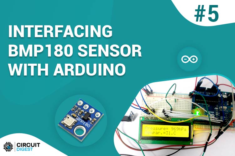
In this tutorial we are going to design a Barometric Pressure Measuring System using BMP180 and ARDUINO. First of all for interfacing BMP180 to ARDUINO, we need to download a library specifically designed for BMP180. This library is available at: https://github.com/adafruit/Adafruit-BMP085-Library After attaching that library, we can call special functions which will ease working with BMP180 sensor.
Components Required
Hardware: Arduino uno board, connecting pins, 220Ω resistor, BMP180 Barometric Pressure Sensor, 16x2 LCD, bread board.
Software: Arduino nightly
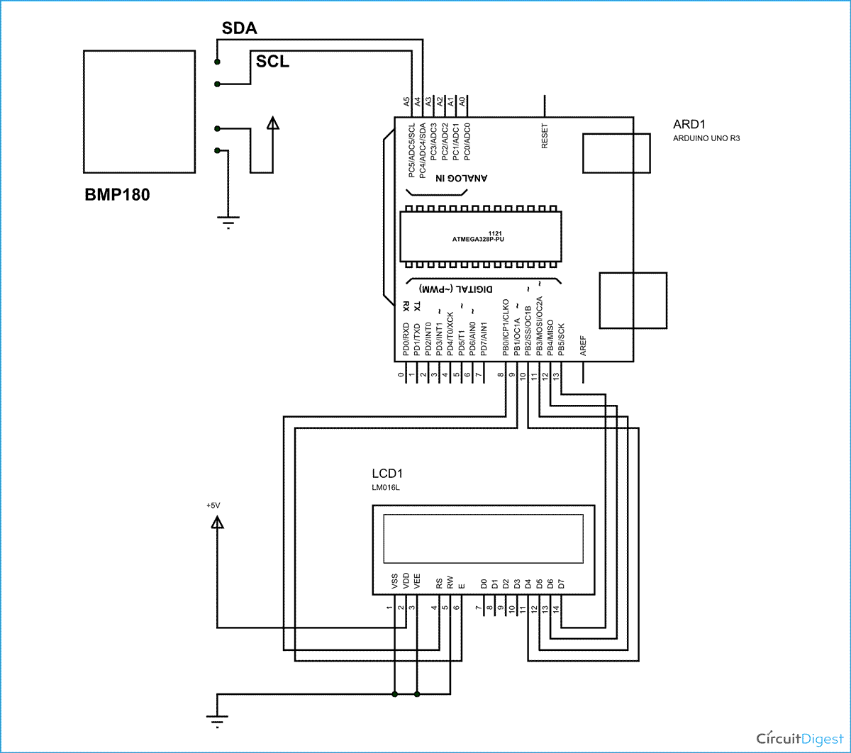
Circuit Diagram & Working Explanation
After calling for header we don't need to worry for establishing communication between Arduino Uno and BMP180 sensor. We can simply call in special functions which will do that for us. We only need to Initialize an LCD and show the called values from SENSOR on it.
In 16x2 LCD there are 16 pins over all if there is a back light, if there is no back light there will be total 14 pins. One can power or leave the back light pins. Now in the 14 pins there are 8 data pins (7-14 or D0-D7), 2 power supply pins (1&2 or VSS&VDD or GND&+5v), 3rd pin for contrast control (VEE-controls how thick the characters should be shown) and 3 control pins (RS&RW&E).
In the circuit, you can observe that I have only took two control pins, the contrast bit and READ/WRITE are not often used so they can be shorted to ground. This puts LCD in highest contrast and read mode. We just need to control ENABLE and RS pins to send characters and data accordingly.
The connections which are done for LCD are given below:
PIN1 or VSS to ground
PIN2 or VDD or VCC to +5v power
PIN3 or VEE to ground (gives maximum contrast best for a beginner)
PIN4 or RS (Register Selection) to PIN8 of ARDUINO UNO
PIN5 or RW (Read/Write) to ground (puts LCD in read mode eases the communication for user)
PIN6 or E (Enable) toPIN9 of ARDUINO UNO
PIN11 or D4 to PIN10 of ARDUINO UNO
PIN12 or D5 to PIN11 of ARDUINO UNO
PIN13 or D6 to PIN12 of ARDUINO UNO
PIN14 or D7 to PIN13 of ARDUINO UNO
The ARDUINO IDE allows the user to use LCD in 4 bit mode. This type of communication enables the user to decrease the pin usage on ARDUINO, unlike other the ARDUINO need not be programmed separately for using it in 4 it mode because by default the ARDUINO is set up to communicate in 4 bit mode. In the circuit you can see wehave used 4bit communication (D4-D7). [Also check: Interface LCD with Arduino Uno]
So from mere observation from above table we are connecting 6 pins of LCD to controller in which 4 pins are data pins and 2 pins for control.
For connecting the BMP180 to Arduino Uno we need to do following:
|
First we need to call the header file for enabling special functions “#include<Adafruit_BMP085.h>”.
With this header file we can call functions that can read values from Sensor directly without any fuzz.
Now we need to enable the C communication, this is done by calling “#include <Wire.h>” header file.
We can read pressure by calling” String PRESSUREVALUE = String(bmp.readPressure());”. Here the pressure value will be read from sensor and is stored in the string “PRESSUREVALUE”.
We can read temparature by calling” String TEMPARATUREVALUE = String(bmp.readTemperature());”. Here the pressure value will be read from sensor and is stored in the string “TEMPARATUREVALUE”.
First we need to enable the header file (‘#include<LiquidCrystal.h>’), this header file has instructions written in it, which enables the user to interface an LCD to UNO in 4 bit mode without any fuzz. With this header file we need not have to send data to LCD bit by bit, this will all be taken care of and we don’t have to write a program for sending data or a command to LCD bit by bit.
Second we need to tell the board which type of LCD we are using here. Since we have so many different types of LCD (like 20*4, 16*2, 16*1 etc.). In here we are going to interface a 16*2 LCD to the UNO so we get ‘lcd.begin(16,2);’. For 16*1 we get ‘lcd.begin(16,1);’.
In this instruction we are going to tell the board where we connected the pins, The pins which are connected are to be represented in order as “RS, En, D4, D5, D6, D7”. These pins are to be represented correctly. Since we connected RS to PIN0 and so on as show in circuit diagram, We represent the pin number to board as “LiquidCrystallcd(0,1,8,9,10,11);”.
After above there all there is left is to send data, the data which needs to be displayed in LCD should be written as “cd.print("hello, world!");”. With this command the LCD displays ‘hello, world!’.
As you can see we need not worry about any this else, we just have to initialize and the UNO will be ready to display data. We don’t have to write a program loop to send the data BYTE by BYTE here. After reading the value from sensor we are going to display them on 16x2 LCD.
Complete Project Code
#include <Adafruit_BMP085.h>
#include <Wire.h>
#include <LiquidCrystal.h>
// initialize the library with the numbers of the interface pins
LiquidCrystal lcd(8, 9, 10, 11, 12, 13);//RS,EN,D4,D5,D6,D7

char PRESSURESHOW[4];// initializing a character of size 4 for showing the  result
char TEMPARATURESHOW[4];// initializing a character of size 4 for showing the temparature result

Adafruit_BMP085 bmp;

void setup() {
                lcd.begin(16, 2);
                // Print a logo message to the LCD.
                lcd.print("  CIRCUITDIGEST");
                lcd.setCursor(0, 1);
                delay (2500);
                delay (2500);

                lcd.clear();//clear display

                // Print another message to the LCd

                Serial.begin(9600);
                if (!bmp.begin())
                {
                                Serial.println("ERROR");///if there is an error in communication
                                while (1) {}
                }
}

void loop()
{


                lcd.print("Pressure= ");          // print name

                String PRESSUREVALUE = String(bmp.readPressure());
                // convert the reading to a char array
                PRESSUREVALUE.toCharArray(PRESSURESHOW, 4);
                lcd.print(PRESSURESHOW);
                lcd.print("hPa   ");
                lcd.setCursor(0, 1);
                //// set the cursor to column 0, line 1

                lcd.print("Tempar.=");// print name


                String TEMPARATUREVALUE = String(bmp.readTemperature());
                // convert the reading to a char array
                TEMPARATUREVALUE.toCharArray(TEMPARATURESHOW, 4);
                lcd.print(TEMPARATURESHOW);
                lcd.print("C   ");

                lcd.setCursor(0, 0);/ set the cursor to column 0, line1

                delay(1000);
}
Comments
i am getting error in header file Adafruit_BMP085.h how to solve this? help me...
How can I compose an if ...else statement based on reading temperature and then turning on a digital output on and off or high and low want to turn on an led on when temp is 23 c or below and off on or above 25 c
Check this project: Humidity and Temperature Measurement using Arduino and you can also do it without microcontroller using LM35, check this one: Temperature Controlled LEDs using LM35
sir i want to make a oxygen monitoring pressure sensor with arduino uno with display.
i want it to display pressure of oxygen in BAR or PSI with display on lcd
and i want also switch an alarm when pressure is below 1.2 bar.
can you guide me sir
i have 16 by 2 lcd and arduino uno.
sir iam getting error like this
Could not delete C:\Users\kk\AppData\Local\Temp\build2001913045590785928.tmp\sketch_feb26a.cpp
sketch_feb26a.ino: In function 'void loop()':
sketch_feb26a:113: error: expected primary-expression before '/' token
sketch_feb26a:113: error: 'set' was not declared in this scope
sketch_feb26a:113: error: expected `;' before 'the'
sketch_feb26a.ino: In function 'void loop()':
sketch_feb26a:113: error: expected primary-expression before '/' token
sketch_feb26a:113: error: 'set' was not declared in this scope
sketch_feb26a:113: error: expected `;' before 'the'
getting error in this line
lcd.setCursor(0, 0);/ set the cursor to column 0, line1
What error (Error name)?
Most likely you should have not added the library properly
You filled in:
lcd.setCursor(0, 0);/ set the cursor to column 0, line1
Try it this way:
lcd.setCursor(0, 0); // set the cursor to column 0, line1
wer should we connect the resistor?


Nice work.
just have a quick question.
how much time the the library is taking in calculating the pressure???.