

Internet of Things and Home Automation has really been a hyped topic in the recent days. Building something on our own which can communicate to the World Wide Web and can be accessed from anywhere in the world, really sounds cool doesn’t it?
But, wait!!! It also sounds complicated???....
So did it for me, I thought it would take immense time and skill to build things which can interact with the internet. NO, I was completely wrong, thanks to this fantastic module called the ESP8266 from Espressif Systems. Now, you can easily open your doors for IoT Projects with the help of this module. This low cost, small size module could do wonders and is really simple and easy to use, provided we follow the right steps.
This tutorials aims to introduce you to this ESP8266-01 module and help you get started with it. Perhaps, you have already brought your module and got stuck while trying to using it. Then, you are not alone don’t worry, many people find it very difficult to get started with module because there is no proper guidance or documentation for this module. This is the reason for making this tutorial. Follow the instructions here and you should be able to get your ESP8266-01 module up and running in no time, here we will use FTDI USB to TTL Serial Adapter Module to program the ESP8266. Check the detailed Video at the end of the Tutorial.
Before getting into the topic lets cover some basics about the ESP8266-01 Module.
What is ESP8266?
Most people call ESP8266 as a WIFI module, but it is actually a microcontroller. ESP8266 is the name of the microcontroller developed by Espressif Systems which is a company based out of shanghai. This microcontroller has the ability to perform WIFI related activities hence it is widely used as a WIFI module.
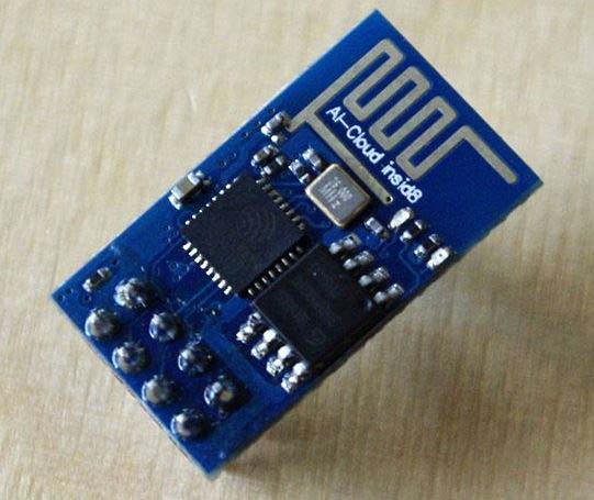
There are many types of ESP8266 module available ranging from ESP8266-01 to ESP8266-12. The one that we are using in the tutorial is the ESP8266-01 because it the cheapest one and easily available. However all the ESP modules have only one type of ESP processor, what differs is only the type of breakout bard used. The breakout board of ESP8266-01 will have only 2 GPIO pins whereas in other boards it will be higher.
The complete specification of the module is given in the below table
|
Voltage |
3.3V |
|
Current Consumption |
10uA-170mA |
|
Maximum current consumption during flashing |
800mA |
|
Flash Memory |
16MB (512K normal) |
|
Processor |
Tensilica L106 32 bit |
|
Processor Speed |
80-160MHz |
|
RAM |
32K+80K |
|
GPIO |
17 (but most are multiplexed) |
|
Analog to digital Converter |
1 (10-bit) |
|
Maximum TCP connections |
5 |
Okay few things which could have surprised you about the specification is that, YES the ESP8266 module comes with a ADC Converter and it does consume a very high current of 0.8A during flashing your device.
Also check our various ESP8266 based interesting IoT Projects.
Basics of WiFi Theory:
Transfer Control Protocol (TCP), Internet Protocol (IP), User Datagram Protocol (UDP), Access Point (AP), Station (Sta), Service Set Identifier (SSID), Application Programming Interface (API), Webserver.....
Do all the above terms make sense to you?
If, yes. Then, BINGO you can jump this part and move to the next section.
If, no. Then you must be one among the many electrical students who just blinked through most these terms just like I did when I was first introduced to all these stuff. So, let us quickly run through all these terms because only then we could make our entry into the world of IOT.
Transfer Control Protocol (TCP):
Most of us would know what this means. Yes, these are the set of rules based on which the internet works. Since ESP8266 has the ability to set up WIFI connections. At a high level Wi-Fi is the ability to participate in the TCP/IP connections over a wireless link. You can make your ESP to work on the TCP/IP protocol or the UDP protocol.
User Datagram Protocol (UDP):
UDP is also another type of internet protocol. This type of communication is faster than TCP but it is less accurate. The reason is that TCP uses an Acknowledgment during its communication but UDP does not. TCP is mostly used in networks where there is a requirement high reliability. UDP is used in places where speed has high priority than reliability. For example UDP is used in video conferencing, because there even if some pixels are not transmitted it will not affect the video quality that much but the speed is very important.
Most of the ESP8266 projects and codes work around the TCP/IP, UDP will be least bothered.
Access Point (AP) and Station (STA):
Once you start working with ESP module, you would come across these two terms frequently. Let us say you and your friend would like to surf the internet on your smart phones but since he does not have an active internet connection you decide to turn on your hotspot and your friend connects to it. Here your phone which is sourcing the internet connection is the Access Point (AP) and your friend’s phone which is using the internet is called the Station (STA).
ESP8266 module can be used in three modes, AP mode, STA mode or in both STA and AP mode (combined).
Service Set Identifier (SSID):
This is fairly a simple term. Almost all of us have used WIFI. The name of the Wi-Fi Network is called its SSID. When we have multiple access points for a station to connect to, the station should know which access point it should get connected, hence each Access Point (AP) is given a identity which is called the SSID.
Application Programming Interface (API):
To put it simple an API is a messenger which takes in your requests, processes it and returns your system the desired result. Most of the activities we do on the internet uses API’s, like when you book a flight, make an online purchase etc. Every websites links you to an API where some part of the work like signing up, making payment etc. is done for you there.
ESP8266 uses API to talk to the world of Internet. For example if it wants to know the time, climate, or whatever it should request in form of an API to the corresponding website. That website will receive the request and give the desired result back to our ESP module.
Web Server:
A web Server is something which is responsible to display the contents of a website. All the contents of that particular website will be loaded into its web server. There are dedicated computers whose job is to only acts as a web server. We can also program our ESP8266 to work as a web server, and connect to it from anywhere in the world.
Okay, this is enough for us to get started. Now, let us get our hands on the hardware.
Types of programming with ESP8266:
There are two of ways to work with your ESP8266 module. This tutorial will help you to get started with both. One way is by using the AT commands. The other way is by using the Arduino IDE. Let us understand what it means.
All ESP8266 modules shipped from the factory will have a default firmware (SDK+API) loaded into it. This firmware will help you to program the ESP8266 module through AT commands.
The other way is by directly programming the ESP8266 module using the Arduino IDE (board not needed) and its libraries. All the projects can be done in both the methods. But, if you start using the Arduino IDE for programming your ESP8266 you might not be able to use AT commands because the default SDK might have been corrupted. In that case you have to flash your ESP with default settings. We will cover that in another tutorial.
Hardware to Program ESP8266 Module:
ESP8266 is an 8 terminal module. The pin out of the same is shown below.
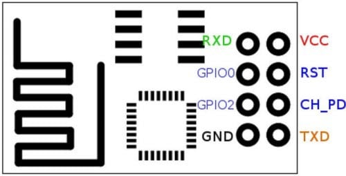
Unfortunately, this module is not breadboard friendly and hence we cannot mount it directly onto our breadboard. Also unlike Arduino it does not have a built in USB to Serial driver; hence we have to use “FTDI USB to TTL Serial Adapter Module” to communicate with it. Make sure that the FTDI board can operate on 3.3V also; the one that we are using in this tutorial is shown below.

Now, as we know we should power up the ESP8266 with 3.3V. But the current consumption is 0.8A, so it might not work as expected if powered from our FTDI breakout board. Hence we have to build our own powering circuit. Here we have used LM317 for the powering purpose; the details for making the complete hardware are given later sections.
Materials Required:
- Perf Board
- ESP8266-01
- FTDI breakout Board
- LM317
- 0.1uf capacitor
- 10uf Capacitor
- Barrel Jack
- Bergstik Male and Female
- Push Button
- Connecting wires
- 12V Adapter to power the board.

Circuit Explanation:
The Schematics of the board is shown below

Some might have tried powering your ESP directly from your FTDI and got it working, but the following are the reasons to build your own board with few additional components:
- Only few FTDI boards can source enough current for the ESP module. Few ESP modules might consume high current than the other during flashing. Hence it is always safe to have your own power source, and it will be easier to integrate powering circuit on Dot Board instead of breadboard.
- We should always reset the ESP module before uploading the code, building our own board will help us to reset the module easily. We have used Push Button to Reset ESP8266.
- The GPIO0 pin has to be grounded when programming using Arduino and must be left free when using AT commands, this can easily be toggled if we build our own board. We have used a Jumper for switching between AT commands mode and Arduino IDE Programming mode.
- All the programming is done using Serial communication, if you use a breadboard some loose terminals might cause an error in half way and force us to flash the module to work with again.
That being said you can select between using a breadboard, and making your own board for programming the module. If you still want to use the breadboard, the same circuit shown above can be build using your breadboard. Only the appearance will be different, all the other instructions in this tutorial will apply the same.
Building Board to Program ESP8266:
So here we are building the board to program ESP8266 module which have its own powering circuit to power up the ESP8266.
As said our module will require around 800mA while programming it. Hence we have constructed our own power module by using a LM317 variable voltage regulator since the source current of LM317 is almost 1.2A. The input voltage of LM317 will be 12V which will be given using a 12V 2A wall mount adapter. The output of the LM317 will be regulated to 3.3V constantly by using the resistors of 220ohm and 360ohm. Also check our Battery Charger Circuit using LM317 to learn more about LM317.
The formulae to calculate the output voltage of LM317 is given below:
Vout = 1.25*(1+ (R2/R1))
Where, R1 is 220ohm and R2 is 360ohms.
The ESP8266 Module is connected as per the pins shown in the table below.
|
Pin No. |
ESP pin name |
Connected to |
|
1 |
Ground |
Ground of the FTDI module |
|
2 |
GPIO2 |
Left free or connected to berg stick for future use |
|
3 |
GPIO0 |
Switch to toggle between programming modes |
|
4 |
Rx |
Tx of FTDI module |
|
5 |
Tx |
Rx of FTDI module |
|
6 |
CH_PH |
3.3V from LM317 |
|
7 |
Reset |
Pushbutton to reset module |
|
8 |
Vcc |
3.3V from LM317 |
To easily toggle between the AT command mode and the Arduino Programming mode I have placed a switch (jumper) which will pull the GPIO 0 to ground when using Arduino IDE and will leave it floating when using the AT commands.
There is a push button which when pressed will reset the ESP module. This is done by simply connecting the RST pin of the ESP module to the ground rail through the pushbutton. Each time before we program our ESP module we should reset it.
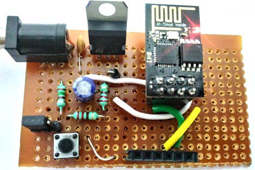
Once you have assembled the circuit it should look something like this below.
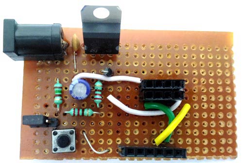
I have used a Perf board but you can also use a breadboard if you are interested (as discussed above). The complete build and explanation is shown in the video below.
Once done with the connections. Power up the board without the ESP & FTDI boards and check if we get 3.3V properly on the Vcc and Ground terminals of the ESP modules position. Now ensure your FTDI board is in 3.3V mode and connect your FTDI and ESP modules to your board.
Power on your adapter and connect it to your board, the ESP module should light up with a red colour.
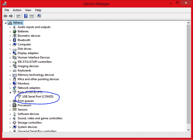
Then connect your FTDI board to your computer using a mini-USB to USB cable and navigate to Device manager on your computer and you should find you FTDI board connected to your COM port, as shown below:
Now time to get our hands on programming our ESP8266 module. You can start with by using the AT-commands and then moving to using the Arduino IDE. Don’t forget to check our other ESP8266 based Projects.
Comments
Link to next step...
Hi Arun,
Thanks for your words...
The continuation is already uploaded you can find it here....
https://circuitdigest.com/microcontroller-projects/how-to-use-at-comman…
There are more yet to come, so hold on
Schematic of programmer board
Hi Brandt,
I do not know what you mean by programmer board here. If you are asking for the FTDI breakout board then its schematics can be found here
https://learn.sparkfun.com/tutorials/using-the-arduino-pro-mini-33v
Also since you are new to electronics, it is not recommended to build you board at this stage. It would be advisory to buy one.
Thanks
Do not worry about that!!!
Do not worry about that!!!
I did not have a 220R resistor so I have used two 110R in series for my hardware. If you have the right value of resistor then use them.
Just follow the circuit diagram and make you connections
Migh be a mistake in the diagram
Please check the diagram shown above, the resistor have a common node between ADJ and Vout pin of the LM317, this does not give a 3.3v output
I took the resistors ont he picture of the board welded and they are differente, still no getting the 3.3 V output
Can you please share an actual diagram or help me understand this?
ESP8266-01
can i olso use ESP-Programmer instead this self made board
I've tried everything but don't get any further
Help
Yes you can
You can use a normal FTDI board or USB to TTL that supports 3.3V and it should work. You can check this out https://iotdesignpro.com/projects/getting-started-with-esp8266-and-prog…

Hello Mr Raj,
Your article "Getting started with ESP8266" seems very useful and informative.
Can you please let me have the link for the continuation ... that is after completing the hardware, how do I use the AT commands thru' FTDI or preferably Arduino board....more details needed please..Thank you...Arun