

Right from the time of industrial age, we mankind have been rapidly developing. With every progress we also pollute our environment and eventually degrading it. Now global warming is an alarming threat and even the air that we breathe are getting critical. So air quality monitoring has also started to gain importance. So in this article we will learn how to use any MQ series gas sensor with Arduino and showing the output in PPM (parts per million). PPM is also expressed as milligrams per litre (mg/L). These sensors are commonly available and are also reliable for measuring different types of gas shown below
MQ-series Gas sensors
- Carbon Dioxide (CO2) : MG-811
- Carbon Monoxide (CO): MQ-9
- Total Volatile Organic Compounds (TVOCs): CCS811
- Equivalent Carbon Dioxide (eCO2): CCS811
- Metal Oxide (MOX): CCS811
- Ammonia: MQ-137
- Air Quality: MQ-135
- LPG, Alcohol, Smoke: MQ2
We have already used MQ2 for smoke sensing and MQ-135 for Air quality monitoring project. Here I will be using the MQ-137 sensor from sainsmart to measure ammonia in ppm. With the sensor in hand I went through all the available tutorials and found that there has no proper documentation on how to measure the gas in ppm. Most tutorials either deal with only the Analog values or introduce some constants which are not reliable for measuring all type of gas. So after fiddling around online for a long time I finally found how to use these MQ series gas sensors to measure ppm using Arduino. I am explaining things from the bottom without any libraries so that you can use this article for any Gas sensor available with you.
Preparing your Hardware:
The MQ gas sensors can either purchased as a module or just as a sensor alone. If your purpose is to measure only ppm then it’s best to buy the sensor alone since the module is good for only using the Digital pin. So if you have purchased the module already then you have to perform a small hack which will be discussed further. For now, let’s assume you have purchased the sensor. The pinout and connection of the sensor is shown below
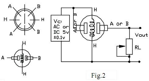
As you can see you just have to connect one end of ‘H’ to supply and the other end of ‘H’ to ground. Then combine both A’s and both B’s. Connect one set to supply voltage and the other to your analog pin. The resistor RL plays a very important role in making the sensor work. So make a note of which value you are using, a value of 47k is recommended.
If you have already purchased a module, then you should track your PCB traces to find the value of your RL in the board. Grauonline has already done this work for us and the circuit diagram of the MQ gas sensor board is given below.
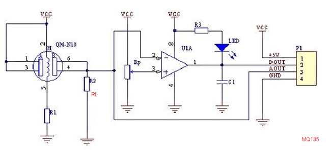
As you can see the resistor RL (R2) is connected between the Aout pin and the ground, so if you are having a module the value of RL can be measured by using a multimeter in resistance mode across Vout pin and Vcc pin of the module. In my sainsmart MQ-137 gas sensor the value of RL was 1K and was located here as shown in the picture below.
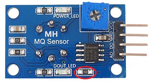
However, the website claims that it provides a variable pot of RL which is not true as you can clearly see in the circuit diagram, the pot is used to set the variable voltage for op-amp and has nothing to do with RL. So we have to manually solder the SMD resistor (1K) shown above and we have to use our own resistor across the Ground and Vout pin which will act as RL. The best value for RL will be 47K as suggested by datasheet hence we are going to use the same.
Approach to Measure PPM from MQ Gas Sensors:
Now that we know the value of RL lets proceed on how to actually measure ppm from these sensors. Like all sensors the place to start is its datasheet. The MQ-137 Datasheet is given here but make sure you find the correct datasheet for your sensor. Inside the datasheet we are need only one graph which will be plotted against (Rs/Ro) VS PPM this is the one that we need for our calculations. So gab it and keep it someplace handy. The one for my sensor is shown below.
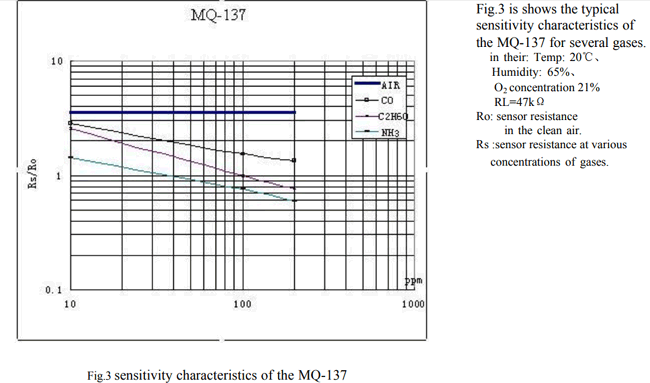
Turns out that MQ137 sensor can measure NH3, C2H6O and even CO. But, here I am interested only in the values of NH3. However you can use the same method to calculate ppm for any sensor you like. This graph is the only source for us to find the value of ppm and if we could somehow calculate the ration of Rs/Ro (X-axis) we can use this graph to find the value of ppm (Y-axis). To find the value of Rs/Ro we need to find the value of Rs and the value of Ro. Where Rs is the Sensor resistance at gas concentration and Ro is the sensor resistance in clean sir.
Yess... this is the plan let’s see how we can get away with this....
Calculating the Value of Ro at Clean Air:
Note that in the graph value of Rs/Ro is constant for air (thick blue line) so we can use this to our advantage and say that when the sensor is working in fresh air the value of Rs/Ro will be 3.6 refer the picture below
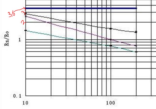
Rs/Ro = 3.6
From the datasheet we also get to have a formula for calculating the value of Rs. The formula is shown below. If you are interested to know how this formula is derived you can read through jay con systems, I would also like to credit them in helping me to sort this out.
![]()
In this formula the value of Vc is our supply voltage (+5V) and the value of RL is the one that we calculated already (47K for my sensor). If we write a small Arduino program we could also find the value of VRL and finally calculate the value of Rs. I have given an Arduino Program below which reads the analog voltage (VRL) of the sensor and calculates the value of Rs using this formula and finally displays it in the serial monitor. The program is well explained through the comment section so I am skipping its explanation here so as to keep this article short.
/*
 * Program to measure the value of R0 for a know RL at fresh air condition
 * Program by: B.Aswinth Raj
 * Website: www.circuitdigest.com
 * Dated: 28-12-2017
 */
//This program works best at a fresh air room with temperaure Temp: 20℃, Humidity: 65%, O2 concentration 21% and when the value of Rl is 47K
#define RL 47  //The value of resistor RL is 47K
void setup() //Runs only once
{
  Serial.begin(9600); //Initialise serial COM for displaying the value
}
void loop() {
  float analog_value;
  float VRL;
  float Rs;
  float Ro;
  for(int test_cycle = 1 ; test_cycle <= 500 ; test_cycle++) //Read the analog output of the sensor for 200 times
  {
    analog_value = analog_value + analogRead(A0); //add the values for 200
  }
  analog_value = analog_value/500.0; //Take average
  VRL = analog_value*(5.0/1023.0); //Convert analog value to voltage
  //RS = ((Vc/VRL)-1)*RL is the formulae we obtained from datasheet
  Rs = ((5.0/VRL)-1) * RL;
  //RS/RO is 3.6 as we obtained from graph of datasheet
  Ro = Rs/3.6;
  Serial.print("Ro at fresh air = ");
  Serial.println(Ro); //Display calculated Ro
  delay(1000); //delay of 1sec
}
Note: The value of Ro will be varying, allow the sensor to pre-heat at least for 10 hours and then use the value of Ro.
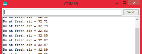
I concluded the value of Ro to be 30KΩ for my sensor (when RL is 47kΩ). Yours might slightly vary.
Measure the value of Rs:
Now that we know the value of Ro we can easily calculate the value of Rs using the above two formulae. Note that the value of Rs that was calculated previously is for fresh air condition and it will not be the same when ammonia is present in the air. Calculating the value of Rs is not a big issue which we can directly take care in the final program.

Relating Rs/Ro ratio with PPM:
Now that we know how to measure the value of Rs and Ro we would be able to find its ratio (Rs/Ro). Then we can use the chart (shown below) to relate to the corresponding value of PPM.
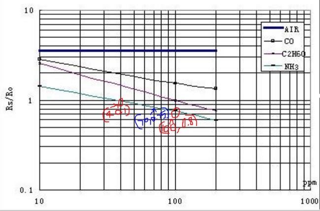
Although the NH3 line (cyan colour) appears to be linear it is actually not linear. The appearance is because the scale is divided un-uniformly for appearance. So the relating between Rs/Ro and PPM is actually logarithmic which can be represented by the below equation.
log(y) = m*log(x) + b
where,
y = ratio (Rs/Ro)
x = PPM
m = slope of the line
b = intersection point
To find the values of m and b we have to consider two points (x1,y1) and (x2,y2) on our gas line. Here we are working with ammonia so the two points I have considered is (40,1) and (100,0.8) as shown in the picture above (marked as red) with red marking.
m = [log(y2) - log(y1)] / [log(x2) - log(x1)]
m = log(0.8/1) / log(100/40)
m = -0.243
Similarly for (b) let’s get the midpoint value (x,y) from the graph which is (70,0.75) as shown in picture above (marked in blue)
b = log(y) - m*log(x)
b = log(0.75) - (-0.243)*log(70)
b = 0.323
That’s it now that we have calculated the value of m and b we can equate the value of (Rs/Ro) to PPM using the below formula
PPM = 10 ^ {[log(ratio) - b] / m}
Program to calculate PPM using MQ sensor:
The complete program to calculate PPM using a MQ sensor is given below. Few important lines are explained below.
Before proceeding with the program we need to feed in the values of Load resistance (RL), Slope(m), Intercept(b) and the value of Resistance in fresh air (Ro). The procedure to obtain all these values have already be explained so let’s just feed them in now
#define RL 47  //The value of resistor RL is 47K
#define m -0.263 //Enter calculated Slope
#define b 0.42 //Enter calculated intercept
#define Ro 30 //Enter found Ro value
Then read the Voltage drop across the sensor (VRL) and convert it to Voltage (0V to 5V) since the analog read will only return values from 0 to 1024.
VRL = analogRead(MQ_sensor)*(5.0/1023.0); //Measure the voltage drop and convert to 0-5V
Now, that the value of VRL is calculated you can use the formula discussed above to calculate the value of Rs and the also the ratio (Rs/Ro)
ratio = Rs/Ro; // find ratio Rs/Ro
Finally, we can calculate the PPM with our logarithmic formula and display it on our serial monitor as shown below
double ppm = pow(10, ((log10(ratio)-b)/m)); //use formula to calculate ppm
Serial.print(ppm); //Display ppm
Showing PPM value on Hardware with Arduino and MQ-137:
Enough of all the theory let us build a simple circuit with the sensor and LCD to display the value of gas in PPM. Here the sensor I am using is MQ137 which measures ammonia, the circuit diagram for my set up is shown below.

Connect your sensor and your LCD as shown in the Circuit diagram and upload the code given at the end of the program. You have to modify the Ro value as explained above. Also make the changes in parameter values if you are using any other resistor as RL other than 4.7K.
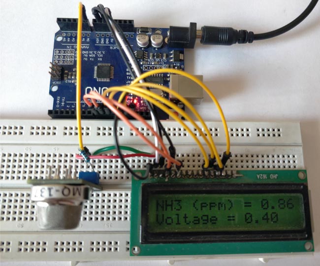
Leave your set-up powered for at least 2 hours before you take any readings, (48 hrs is recommended for more accurate values). This time is called the heating time, during which the sensor warms up. After this, you should be able to see the value of PPM and the voltage displayed on your LCD screen as shown below.
Now to ensure if the values are really related to the presence of ammonia, let’s place this set-up inside a closed container and send ammonia gas inside it to check if the values are increasing. I do not have a proper PPM meter with me calibrate it and it would great if someone with meter could test this set-up and let me know.
You can watch the video below to check how the readings varied based on the presence of ammonia. Hope you understood the concept and enjoyed learning it. If you have any doubts leave them in the comment section or for more detailed help use the forum here.
Complete Project Code
/*
 * Program to measure gas in ppm using MQ sensor
 * Program by: B.Aswinth Raj
 * Dated: 28-12-2017
 */
#define RL 47  //The value of resistor RL is 47K
#define m -0.263 //Enter calculated Slope
#define b 0.42 //Enter calculated intercept
#define Ro 20 //Enter found Ro value
#define MQ_sensor A0 //Sensor is connected to A4
#include <LiquidCrystal.h> //Header file for LCD from https://www.arduino.cc/en/Reference/LiquidCrystal
const int rs = 8, en = 9, d4 = 10, d5 = 11, d6 = 12, d7 = 13; //Pins to which LCD is connected
LiquidCrystal lcd(rs, en, d4, d5, d6, d7);
void setup() {
  lcd.begin(16, 2); //We are using a 16*2 LCD display
  lcd.print("NH3 in PPM"); //Display a intro message
  lcd.setCursor(0, 1);   // set the cursor to column 0, line 1
  lcd.print("-CircuitDigest"); //Display a intro message
   delay(2000); //Wait for display to show info
   lcd.clear(); //Then clean it
}
void loop() {
  float VRL; //Voltage drop across the MQ sensor
  float Rs; //Sensor resistance at gas concentration
  float ratio; //Define variable for ratio

  VRL = analogRead(MQ_sensor)*(5.0/1023.0); //Measure the voltage drop and convert to 0-5V
  Rs = ((5.0*RL)/VRL)-RL; //Use formula to get Rs value
  ratio = Rs/Ro;  // find ratio Rs/Ro

  float ppm = pow(10, ((log10(ratio)-b)/m)); //use formula to calculate ppm
  lcd.print("NH3 (ppm) = "); //Display a ammonia in ppm
  lcd.print(ppm);
  lcd.setCursor(0, 1);   // set the cursor to column 0, line 1
  lcd.print("Voltage = "); //Display a intro message
  lcd.print(VRL);
   delay(200);
   lcd.clear(); //Then clean it
}
Comments
this is helpful
VERY NICE AND GOOD WORK
Sir your value in LCD is 0.86ppm. How can you relate that with the NH3 Odor Threshold value of 0.037ppm and NH3 Recognition Threshold of 46.8ppm???
Sorry Archie cant get your question!! Where did you get this threshold value of 0.037ppm?
Hi, I closed this slip, but the voltage is 0.40. 00 ppm. The problem is where is the thank you.
Mr.
Please correct a small error, the value of the resistor RL on the PCB is 1K, which should be replaced by one of 47K, but RL is not the one indicated (which is a 10K), RL is next to 5R1 on the Photography.
Now the problem really is the value of RL that is needed (47K), it will cause inaccurate reading values in the ADC ...
"The ADC is optimized for analog signals with an output impedance of approximately 10 kΩ or less. If such
a source is used, the sampling time will be negligible. If a source with higher impedance is used, the
sampling time will depend on how long time the source needs to charge the S/H capacitor, with can vary
widely. The user is recommended to only use low impedance sources with slowly varying signals, since
this minimizes the required charge transfer to the S/H capacitor."
(extracted from 28.6.1 Analog Input Circuitry of Atmega328P datasheet)
http://ww1.microchip.com/downloads/en/DeviceDoc/Atmel-42735-8-bit-AVR-Microcontroller-ATmega328-328P_Summary.pdf
Man this is just what i needed to carry out my research thanks man!!!!!!!!!!!!!!!!!
Thanks a lot. I tried applying the same to the MQ-136 sensor for reading hydrogen sulfide. The graph is exactly the same. So I noticed one thing for calculating b: The result of your formula is not correct. Also the ratio value of the point should be 0.85, not 0.75.
Thanks, this really help me to finish my project
Hey sir, how yoy calculated intercept to get value b = log(0.75) - (-0.243)*log(70)
b = 0.323. I try with wolfram and get better value. Can you explain this?
Thank you so much for sharing this. However, I just started to read Ro and it is showing me negative values. I am not sure if that happened to you. I hope in 10 hours start to display positive values.
Its weird that you get negative values. I have never seen negative values. Anyways let us know how it turns out!!
Reading Ro was a failure I had to print Ro as negative in my code to get the positive value in the serial monitor and the maximum value I got was 13. I think it happened because I used a broken input cable to my arduino Leonardo which I hope I did not damage it so I bought a cheap arduino UNO. I already have the reference that Ro should be between 20 and 30. So after that, it was ok. I was able to read NH3. But there is an issue, if you do the math you will notice that in the video shows this example VRL = 0.40 Rs = (5(RL)/VRL) - RL if RL = 47 (47k ohms) Rs = 540 then ppm = pow (10, ( log10 (540/30) - 0.42)/ -0.263 ) = > ppm = pow (10, -3.17) => ppm = 0.0006 exactly this is a small number. However in the video shows VRL = 0.40 ppm= 0.86. I thought I had some kind of error but doing math ppm = 0.0006. Because it is a small number my LCD does not show that number and the ideal is to read a big range of NH3. I decided to multiply ppm for 10.000 in order to get more range. What do you think ...
What is the range of NH3 you are trying to measure, check if it is within the range of graph in the datasheet
Thaks for replying me. Well the datasheet shows that MQ137 reads from 5 to 200ppm NH3. I just saw that ppm it is too small to see it from the lcd so I just multiply for 1.000 to see something. Perhaps I cannot say that my sensor is able to read from 0 to 5000 but I hope those readings are able to show when the compost decrease its ammonia.
Multiply by 1.00? I cant get the idea.
Anyways don't relay too much in these sensors they are decent enough only to give you a rough idea
You did a mistake. Your Calculating the Value of Ro at Clean Air was incorrect since this is a log scale graph.
It shoud be 3.4-3.5.
The (x,y) coordinate that you get also a rough estimate.
This leaded you to an incorrect gas concentration.
Hi, I'm beginning to work on this project.
So, for RL, I should replaced the 1kohm SMT resister with a 47kohm SMT resistor ?
"we have to manually solder the SMD resistor (1K) shown above ", do you mean remove this 1k ohm resistor?
sorry for the confusion there. yes you should replace the 1k smd with 47k
I'm reading negative values from Ro. I already changed the cables and the sensor. What else could be causing this wrong reading?
Did you allow the sensor to heat up for some-time.
Hello,
I'm reading the Ro and I'm getting negative values, I made the cable change, the mq137 sensor, the mega sensor, I left 24 hours reading and I still get negative values.
I am using the proposed code without any changes.
I changed my code, because it seemed that with each loop the voltage was being added to the previous one. Try to use:
#define RL 47 //The value of resistor RL is 47K
void setup() //Runs only once
{
Serial.begin(9600); //Initialise serial COM for displaying the value
}
void loop() {
float analog_value;
float VRL;
float Rs;
float Ro;
analog_value=0; //I added this line to zero my variable read at the beginning of each loop
for(int test_cycle = 1 ; test_cycle <= 500 ; test_cycle++) //Read the analog output of the sensor for 200 times
{
analog_value = analog_value + analogRead(A0); //add the values for 200
}
analog_value = analog_value/500.0;
VRL = analog_value*(5.0/1023.0);
Rs = ((5.0/VRL)-1) * RL;
Ro = Rs/3.6;
Serial.print("VRL = ");
Serial.println(VRL);
Serial.print("Rs = ");
Serial.println(Rs);
Serial.print("Ro at fresh air = ");
Serial.println(Ro);
Serial.print("-----------------------------------------------------------------------");
delay(1000); //delay of 1sec
Dear peple,
after some strugling around negative values for R0 I did discover that it is compulsory to inizialize the summation (analog_value) to zero. I.E. :
float analog_value=0;and, just to be more elegant, in the summation I write:
analog_value += analogRead(A0);
insted
analog_value = analog_value + analogRead(A0);
What are the values of R1, RP, R3, C1 ? Also is there any specific opamp I will have to use ? I am planning to use TLV9001
Sir, where and how to get that table? Did you use any device to measure every graph? The figures above in the Rs/Ro? Sorry but enlighten me about it.


This is really helpful