
This Arduino based Real time clock is a digital clock to display real time using a RTC IC DS1307 which works on I2C protocol. Real time clock means it runs even after power failure. When power is reconnected, it displays the real time irespective to the time and duration it was in off state. In this Arduino alarm clock project we have used a 16x2 LCD module to display the time in - "hour, minute, seconds, date, month and year" format. An Alarm option is also added and we can set up the alarm time. Once alarm time it saved in internal EEPROM of arduino, it remains saved even after reset or electricity failure. Real time clocks are commonly used in our computers, houses, offices and electronics device for keeping them updated with real time.
I2C protocol is a method to connect two or more devices using two wires to a single system, and so this protocol is also called as two wire protocol. It can be used to communicate 127 devices to a single device or processor. Most of I2C devices run on100Khz frequency.
Steps for data writing master to slave (slave receiving mode)
- Sends START condition to slave.
- Sends slave address to slave.
- Send write bit (0) to slave.
- Received ACK bit from slave
- Sends words address to slave.
- Received ACK bit from slave
- Sends data to slave.
- Received ACK bit from slave.
- And last sends STOP condition to slave.
Steps for data reading from slave to master (slave transmitting mode)
- Sends START condition to slave.
- Sends slave address to slave.
- Send read bit (1) to slave.
- Received ACK bit from slave
- Received data from slave
- Received ACK bit from slave.
- Sends STOP condition to slave.
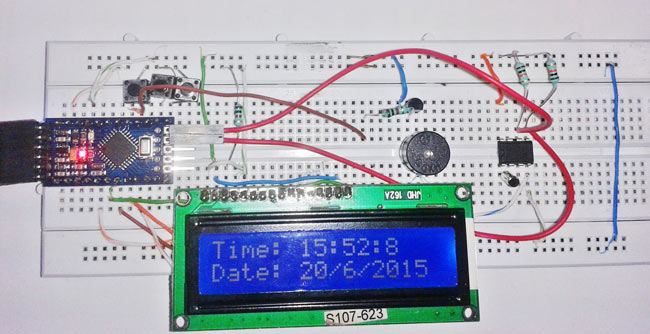
To build this RTC DS1307 IC based digital clock, we have used here Arduino Pro Mini, but you can also use any other Arduino model such as Arduino Uno or Arduino Nano. Along with the Arduino board, DS1307 RTC IC, we have used 16x2 LCD module to display the time and date, a crystal osciallator, 7805 voltage regulator, a buzzer and few transistors and resistors.
Circuit Diagram and Description

In this Arduino based digital clock circuit, we have used three major components which are IC DS1307, Arduino Pro Mini Board and 16x2 LCD module.
Here arduino is used for reading time from ds1307 and display it on 16x2 LCD. DS1307 sends time/date using 2 lines to arduino. A buzzer is also used for alarm indication, which beeps when alarm is activated. A block diagram is shown below to understand the working of this Real Time Clock.
As you can see in the circuit diagram, DS1307 chip pin SDA and SCL are connected to arduino pins SDA and SCL with pull up resistor that holds default value HIGH at data and clock lines. 32.768KHz crystal oscillator is connected with DS1307 chip for generating exact 1 second delay, and a 3 volt battery is also connected to pin 3rd (BAT) of DS1307 which keeps time running after electricity failure. 16x2 LCD is connected with arduino in 4-bit mode. Control pin RS, RW and En are directly connected to arduino pin 2, GND and 3. And data pin D0-D7 is connected to 4, 5, 6, 7 of arduino. A buzzer is connected with arduino pin number 13 through a NPN BC547 transistor having a 1 k resistor at its base.
Three buttons namely set, INC and Next are used for setting alarm to pin 12, 11 and 10 of arduino in active low mode. When we press set, alarm set mode activates and now we need to set alarm by using INC button and Next button is used for moving to digit. The complete breadboard setup of this real time clock with alarm is shown in below image. You can also check a detailed tutorial on digital alarm clock with AVR microcontroller.
Program Description
To program for this real time clock, we have used some libraries for extracting time/date from DS1307 and for displaying on LCD, which are given below:

And initialization of RTC, LCD and input output are performed in setup loop.

Rest of things like reading time, setting alarm is performed in void loop section.

Complete Project Code
/* ----- C Program for Arduino based Alarm Clock ---- */
#include <Wire.h>
#include<EEPROM.h>
#include <RTClib.h>
#include <LiquidCrystal.h>
LiquidCrystal lcd(3, 2, 4, 5, 6, 7);
RTC_DS1307 RTC;
int temp,inc,hours1,minut,add=11;
int next=10;
int INC=11;
int set_mad=12;
#define buzzer 13
int HOUR,MINUT,SECOND;

void setup()
{
 Wire.begin();
 RTC.begin();
 lcd.begin(16,2);
 pinMode(INC, INPUT);
 pinMode(next, INPUT);
 pinMode(set_mad, INPUT);
 pinMode(buzzer, OUTPUT);
 digitalWrite(next, HIGH);
 digitalWrite(set_mad, HIGH);
 digitalWrite(INC, HIGH);

   lcd.setCursor(0,0);
   lcd.print("Real Time Clock");
   lcd.setCursor(0,1);
   lcd.print("Circuit Digest ");
    delay(2000);

 if(!RTC.isrunning())
 {
 RTC.adjust(DateTime(__DATE__,__TIME__));
 }
}

void loop()
{
   int temp=0,val=1,temp4;
   DateTime now = RTC.now();
   if(digitalRead(set_mad) == 0)      //set Alarm time
   {
     lcd.setCursor(0,0);
     lcd.print("  Set Alarm  ");
    delay(2000);
    defualt();
    time();
    delay(1000);
    lcd.clear();
    lcd.setCursor(0,0);
    lcd.print("  Alarm time ");
    lcd.setCursor(0,1);
    lcd.print(" has been set  ");
    delay(2000);
 }
 lcd.clear();
 lcd.setCursor(0,0);
 lcd.print("Time:");
 lcd.setCursor(6,0);
 lcd.print(HOUR=now.hour(),DEC);
 lcd.print(":");
 lcd.print(MINUT=now.minute(),DEC);
 lcd.print(":");
 lcd.print(SECOND=now.second(),DEC);
 lcd.setCursor(0,1);
 lcd.print("Date: ");
 lcd.print(now.day(),DEC);
 lcd.print("/");
 lcd.print(now.month(),DEC);
 lcd.print("/");
 lcd.print(now.year(),DEC);
 match();
 delay(200);
}
void defualt()
{
  lcd.setCursor(0,1);
  lcd.print(HOUR);
  lcd.print(":");
  lcd.print(MINUT);
  lcd.print(":");
  lcd.print(SECOND);
}
/*Function to set alarm time and feed time into Internal eeprom*/
void time()
{
  int temp=1,minuts=0,hours=0,seconds=0;
    while(temp==1)
    {
     if(digitalRead(INC)==0)
     {
      HOUR++;
      if(HOUR==24)
      {
       HOUR=0;
      }
      while(digitalRead(INC)==0);
     }
     lcd.clear();
      lcd.setCursor(0,0);
    lcd.print("Set Alarm Time ");
   //lcd.print(x);
    lcd.setCursor(0,1);
    lcd.print(HOUR);
    lcd.print(":");
    lcd.print(MINUT);
    lcd.print(":");
    lcd.print(SECOND);
    delay(100);
    if(digitalRead(next)==0)
    {
      hours1=HOUR;
      EEPROM.write(add++,hours1);
     temp=2;
     while(digitalRead(next)==0);
    }
    }

    while(temp==2)
    {
     if(digitalRead(INC)==0)
     {
      MINUT++;
      if(MINUT==60)
      {MINUT=0;}
      while(digitalRead(INC)==0);
     }
     // lcd.clear();
    lcd.setCursor(0,1);
    lcd.print(HOUR);
    lcd.print(":");
    lcd.print(MINUT);
    lcd.print(":");
    lcd.print(SECOND);
    delay(100);
      if(digitalRead(next)==0)
      {
       minut=MINUT;
       EEPROM.write(add++, minut);
       temp=0;
       while(digitalRead(next)==0);
      }
    }
    delay(1000);
}

/* Function to chack medication time */
void match()
{
  int tem[17];
  for(int i=11;i<17;i++)
  {
    tem[i]=EEPROM.read(i);
  }
  if(HOUR == tem[11] && MINUT == tem[12])
  {
   beep();
   beep();
   beep();
   beep();
   lcd.clear();
   lcd.print("Wake Up........");
   lcd.setCursor(0,1);
   lcd.print("Wake Up.......");
   beep();
   beep();
   beep();
   beep();
  }
}
/* function to buzzer indication */
void beep()
{
   digitalWrite(buzzer,HIGH);
   delay(500);
   digitalWrite(buzzer, LOW);
   delay(500);
}
Comments
Can i set more than one laram at a time...?
I am using Arduino uno and Arduino IDE 1.6.6 compailer, and when i compile the code he say that beep was not declared, any help?
Define the beep() function properly, check the code above.
Please add a close curly bracket before beep function.
if i set the alarm it can alarm everyday?
what is the purpose of set alarm 2,3,4,5??
thanks.
pls how can i use this code to switch on relay at a set time for 8 seconds and delay for 30 minutes
there are many errors in the 1.65 version of arduino
I am using arduino uno. While compiling error appears like following.
{RTC_DS1307 does not name a type.}
Any help ....
@angelserra @Muhammad Include RTClib.h Library and use latest version of Arduino Software.
is there a snooze button?
please help it has error on the RTC_DS1307 RTC;
Is there any printed circuit board diagram that can you show ?
Can you explain what is arduino ?
Are this project cost really expensive ?
Can this project be done in 4 month or less than that ?
I am using Arduino: 1.6.8 (Windows 10), Board: "Arduino/Genuino Uno"
I put the same code but I got this error message:
Library can't use both 'src' and 'utility' folders. Double check C:\Program Files (x86)\Arduino\hardware\arduino\avr\libraries\Wire
Error compiling for board Arduino/Genuino Uno.
Plz help !!
usefull!, but please can you help me to set more than one alarm
Can you please suggest how to use Adafruit trinket 3.3V in place of Uno and still get a digital clock?
i'm simualate on protues . i see after a period lcd be blink !
can you hepl me ? thank you very much ?
thank you
when alarm on i must rest arduino to active another alarm
the project seems to work fine but the date and time are wrong. How should I correct it?
the date and time are wrong how should we set them peoperly?
Current Code already has provision to set the time to 'now' (DateTime now = RTC.now();). Further check this article for set the current time: arduino-info(dot)wikispaces(dot)com/DS1307_RealTime_Clock_Brick (replace dot with .)
exit status 1
'beep' was not declared in this scope
I am using arduino uno. While compiling error appears like following.
{RTC_DS1307 does not name a type.}
plz do needful
For each include like the following, you will need to have installed the library. Google how to install arduino libraries.
#include <RTClib.h>
good
Can i use arduino uno for making this project..please reply ..thank you..
I want to set alarm date wise. for example I want to set 3 month future date and time. Can I be possible ?
Can this be used to set the alarm for multiple intervals throughout the day and week?
can we replace arduino mini with arduino uno . while by doing this does we need to change the code or circuit
You can use same code and circuit, just take care of pin no in circuit and in code.
Right now the alarm works just once. To make it right, we have to just reset the value of the add to 11 int he void match().
In all just write this part (mentioned below) before the ending of the void match()
add = 11;
Thanks for the code Saddam!!
I would like to use this timer clock as fish feeder. Can some one help with the code to run servo motor instead of alarm? Like the code in instrutable link below?
http://www.instructables.com/id/Arduino-Fish-Feeder/step3/Wiring-and-Programing/
Hi we are conducting a Thesis Project "Real Time Clock alarm with buzzer using arduino device.
we are having a hard time for the set up but the video given was useful for us, we ask if You guys/admins can help us for the codes, tutorials for setting the kit and diagrams so our Thesis Project will function successfully, We are graduating students of Palawan State University, Puerto Princesa City, Palawan. we are hoping for the response Thank you. :)
Sir,plz gave list of equipment used in that project.which arduino can i use po mini or uno.
if(HOUR == tem[11] && MINUT == tem[12])
i want to know what is tem(11 )and tem( 12) stands for ?
I am not getting the output on LCD in proteus. the LCD is just on but the msg is not displayed.what shall
i do??
Sir,i have loaded your code in to Arduino Uno,it compiled successfully without any error, but it not displaying anything in LCD. Only block comes n goes.
Pl tell me etc module required any previous string time before your code loading,if any pl tell me procedure to set RTc modules before loading your codes.
Thanks n pl reply,
Ramesh
I found the solution in code where liquid crystal(3,2,4,5,6,7) replace it by liquid crystal(2,3,4,5,6,7).
what is the use of RTClib.h function?and why it gives an error in arduino uno ide software? any help
RTClib library has functions related to RTC, which we have used in our program. Install the Library properly.
Sir,i have loaded your code in to Arduino Uno,it compiled successfully without any error, but it not displaying anything in LCD. Only block comes and goes. but time is working good and alarm also working but on display blocks comes and goes and nothing displaying correctly.
What the error is plz tell me.
Thanks in advance.
I found the solution in code where liquid crystal(3,2,4,5,6,7) replace it by liquid crystal(2,3,4,5,6,7).
Dear sir, admin,
thank you for the project , i am a beginner and i have a request to make alarm in every 30 miniuts ,
please help me to do a write a code for it.
thanks and regards
can this program work for atmega128?
How can i use 4x4 keypad instead of push button ?
R/Sir
How can I interface jammer with this circuit plz help me........
Hi!
I see that we can set multiple alarms given that once you set the alarms they go up to 9. What part of the code should i change to set only 1 alarm?

Thanks it's usefull